 |
|||
|
|
|||
|
|
|||
| ||||||||||
|
|
 TM 10-3930-633-12
a. General The accelerator linkage consists of
the pedal, a bell-crank lever, and a flexible push-
pull control cable which is connected to the
carburetor. Ball joints are provided at both ends
of the push-pull cable to eliminate twisting,
kinking, and binding. This linkage group also
includes the manual push-pull choke control
cable.
b. Inspection and Adjustment. The linkage
and cable arrangement is properly adjusted when
the vehicle leaves the factory. However, in time
components will become worn and require ad-
justment to maintain smooth, even, control of
engine speed. Proceed as follows:
(1) Check pedal and pedal lever for secure
mounting. Make certain the nylon roller on the
underside of the pedal is in good condition.
(2) Check ball joints at each end of cable for
general condition and secure attachment.
(3) Check entire length of cable for kinks,
permanently deformed bends, or pinched spots.
(4) Check clips, brackets and cable mount-
ings for secure mounting.
(5) Check return spring for secure at-
tachment and adequate tension to return linkage
to idle when pedal is released.
(6) Disconnect the cable from the carburetor
linkage at the ball joint connection to the main
throttle lever.
(7) Adjust cable length by loosening the clip
(29, fig. 4-29) and positioning cable so that
carburetor reaches the full throttle position just
as the accelerator pedal contacts the floor board.
Reconnect cable to carburetor throttle linkage.
(8) After adjustment, make certain that
cable clips and attaching points are secure and
properly aligned.
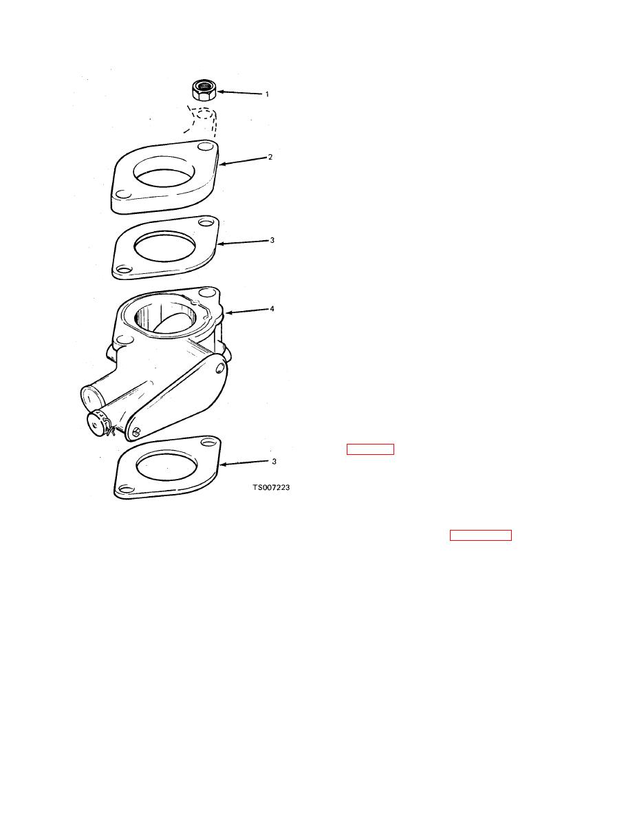
3. Gasket
1. Nut
c. Replacement. Refer to figure 4-31 for parts
4. Governor
2. Adapter
relationship of the accelerator linkage parts, and
remove and replace parts as shown in the ex-
ploded view.
|
|
Privacy Statement - Press Release - Copyright Information. - Contact Us |
