 |
|||
|
|
|||
|
Page Title:
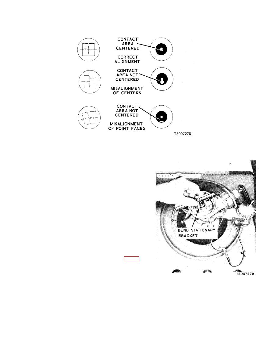
Figure 4-11. Point Alignment Chart |
|
||
| ||||||||||
|
|
 TM 10-3930-633-12
Compression pressure, PSI 140-170
1-5-3 -6-2-4
Firing
order
Engine idle speed, RPM . . . . 500 to 550
(transmission in drive range)
Engine idle manifold vacuum
(in./Hg) . . . . . . . . . . . . . ...17
Initial timing advance 6 BTDC
(vacuum line disconnected)
Maximum governed speed:
No
load
2750
RPM
Loaded . . . . . . . . . . . . . . 2600 RPM
0-4 at 8 in.
Vacuum advance (1000 RPM)
(degrees at in./Hg vacuum 4-7 at 10 in.
5.5-8.5 at 17 in.
S p a r k plug gap (inches) 0.0320.036
Breaker arm spring tension 1721 oz
Breaker point gap (inches) 0.0240 .026
Dwell angle at idle 35 to 38
b. Align the breaker points to make full face
contact by bending the stationary breaker point
bracket. Do not bend the breaker arm. See figure
4-12.
|
|
Privacy Statement - Press Release - Copyright Information. - Contact Us |
