 |
|||
|
|
|||
|
Page Title:
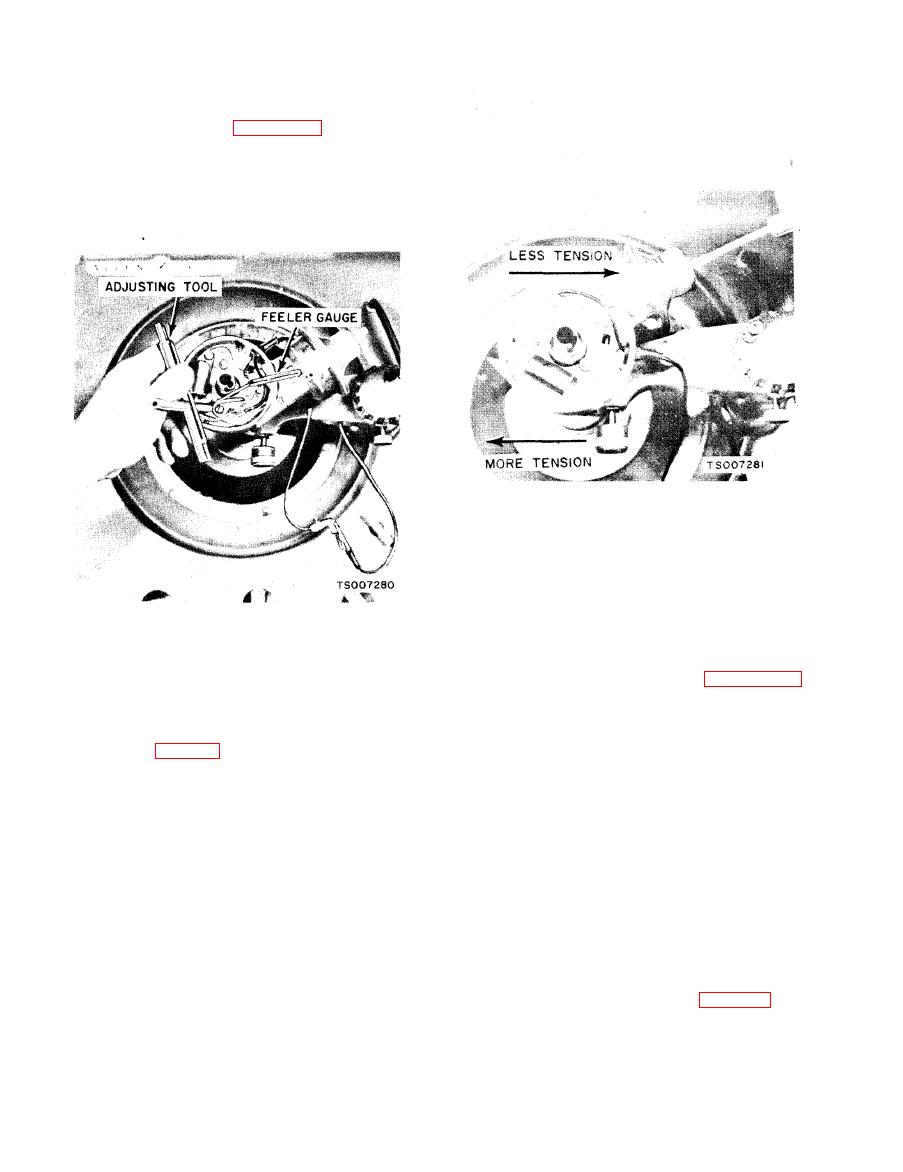
Figure 4-13. Adjusting Point Gap |
|
||
| ||||||||||
|
|
 TM 10-3930-633-12
c. After aligning breaker points, adjust
breaker point gap to 0.024-0.026 inch. Use a wire
feeler gage as shown in figure 4-13 to check the
point opening. If the point gap is not 0.025 inch,
loosen the lock screw with a screwdriver and
position the adjusting plate of the point set until
the correct point opening is attained. Tighten the
lock screw.
The ignition timing mark is a stamped line on the
torque converter to flywheel flexplate. This line is
viewed through a hole in the engine rear cover-
plate, on the lower left side of the engine. A
rubber snap-in cover is used in this opening to
prevent entry of dust, dirt, and moisture. When
4-37. Breaker Point Spring Tension Adjustment
the cover is removed, the timing mark is viewed
through the hole as shown- in figure 4-15.
To check the spring tension, place the hooked end
Degree marks from TDC (0) to 14 (14 before top
of a spring tension gage over the movable breaker
dead center, No. 1 piston) are marked on the
point, then pull the gage at a right angle (900, to
engine rear coverplate. By connecting a timing
the movable arm until the breaker points just
light to the No. 1 (front) spark plug, and aiming
start to open (fig. 4-14). If the spring tension is
the light at the timing marks, the ignition timing
not between 17-21 ounces, it must be adjusted. To
can be determined and adjusted as required.
adjust the spring tension, proceed as follows:
Proceed as outlined below:
a. Clean and mark the timing marks with chalk
at. the breaker point assembly primary terminal.
or white paint.
b. Loosen the nut holding the spring in
b. Disconnect the vacuum line and plug the
posit ion. Move the spring toward the breaker arm
vacuum line to prevent leaks.
pivot to decrease tension and in the opposite
c. Connect a timing light to a terminal of the
direction to increase tension.
No. 1 cylinder spark plug wire. Connect
c. Tighten the locknut, then check spring
tachometer to the engine.
tension. Repeat the adjustment until the specified
d. Start the engine and reduce the engine idle
spring tension is obtained.
speed to 600 RPM to be sure that the centrifugal
advance is not operating. Adjust the initial
w i t h the lockwashers and tighten the nut
ignition timing to specifications (see table 4-4) by
securely.
|
|
Privacy Statement - Press Release - Copyright Information. - Contact Us |
