 |
|||
|
|
|||
|
Page Title:
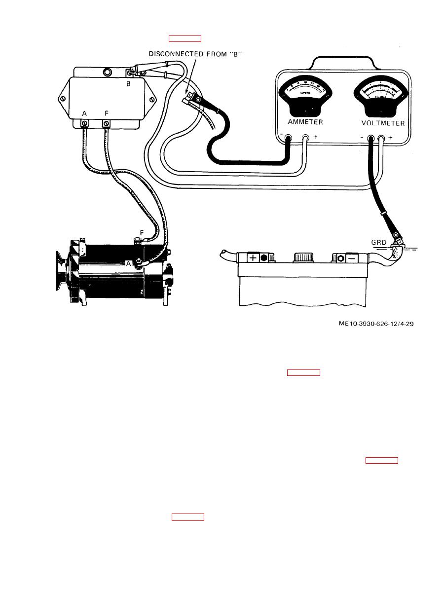
Figure 4-29. Voltage regulator test setup. |
|
||
| ||||||||||
|
|
 (b) Electrical test.
requires two checks and adjustments as follows:
2. Run engine at 1500 rpm.
3. Turn on headlights and if necessary,
(a) Air gap. W i t h b a t t e r y d i s c o n n e c t e d ,
check air gap (fig. 4-27). Insert gage on contact
apply load across battery until test ammeter reads
point side of air gap next to armature stop rivet. If
approximately 7 amperes.
adjustment is needed, loosen bracket adjusting
4. Cycle regulator by reducing speed
screw and raise or lower contact point bracket until
until cutout relay points open, then slowly increase
speed again to 1500 rpm.
a gap of 0.048 to 0.052 inch is obtained. Tighten
b r a c k e t adjusting screw securely after making
adjustment. When armature is held down so that
voltage regulator unit. Reading should be 14.2 to
stop rivet rests on magnet core, point gap should be
14.8 volts.
a minimum of 0.012 inch.
(b) Electrical test.
dirty or pitted contact points.
6. W h e n a d j u s t i n g v o l t a g e r e g u l a t o r ,
2. Run engine at 2000 rpm.
repeat steps 4 and 5 above after each adjustment
3. Apply a variable load across battery
and before taking final reading. Final test reading
until ammeter reading is maximum.
m u s t be made with cover in place at normal
4. Maximum ammeter reading indicates
operating temperature.
setting of current regulator unit. Reading should be
7. If voltage regulator is not within limits,
30 amperes.
bend lower armature spring anchor (fig. 4-27) to
obtain proper voltage.
burned or pitted contact points.
(3) Current regulator. The current regulator
|
|
Privacy Statement - Press Release - Copyright Information. - Contact Us |