 |
|||
|
|
|||
|
|
|||
| ||||||||||
|
|
 idle adjusting screw (34), high idle adjusting screw
(2) If necessary. remove the governor cover
(item 9, fig. 5-20). Turn the low idle adjusting
(29) and spring (30).
(6) On the face of the fuel injection pump
screw (34) counterclockwise or clockwise as
housing, install the packing (61), piston and valve
required to correct low idle speed.
assembly (62), servo cylinder (66), locking plate
(3) Check engine speed with the governor set
in the high idle rpm position. Tachometer in-
(64) and bolts (63).
dication should be 2000 rpm.
(7) Install the weight assembly to the servo
cylinder (66) and secure with the snap ring (65).
(4) Turn the high idle adjusting screw (29) as
necessary to correct-the high idle speed.
(8) Install the ring (68), bearing races (69),
bearing (70), spring (72) and seat (71). Install the
(5) Place the governor control lever in an
washers (73) and full load stop pin (74). Install the
intermediate setting rpm then recheck low idle and
seat (76) and secure with pin (75). Install the
high idle settings. Repeat adjustments as necessary.
spring washer (78), spring (79), and plunger (80).
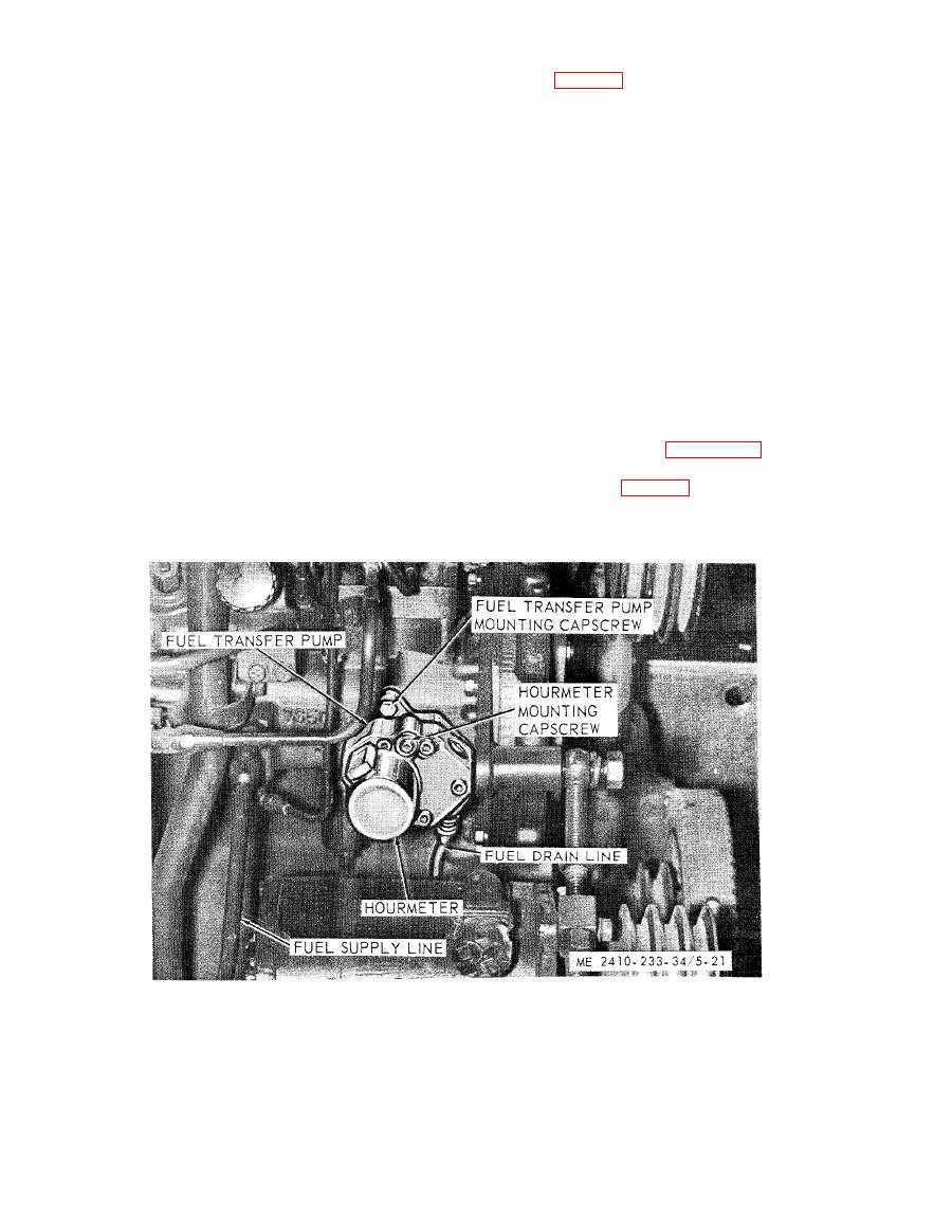
5-13. Fuel Transfer Pump
(9) Install the adjusting screw (38) and bolt
a. General. T h e
self
priming
positive
(36) in the collar (39). Install the locknut (37).
displacement gear type transfer pump delivers a
Install the cover (9) with the bolts (8).
constant supply of diesel fuel. The fuel transfer .
(10) Complete reassembly of engine governor
pump forces fuel through a drilled passage to the
by reversing disassembly procedure.
outside of the fuel filter element. A spring loaded
f. Installation. Install the governor in the
by-pass valve is located in the fuel filter housing to
reverse order of removal. Check and adjust the idle
maintain a maximum pressure of 15 psi.
speed settings (subpara g ) as necessary.
g. Adjustment.
the fuel transfer pump from the engine.
(1) Using a tachometer known to be accurate,
c. Disassembly (fig. 5-22).
check engine speed with the governor set in the low
(1) Remove the bolt (1), gasket (2), spring (3)
idle rpm position. Tachometer indication should be
and plunger (4).
650 rpm.
|
|
Privacy Statement - Press Release - Copyright Information. - Contact Us |
