 |
|||
|
|
|||
|
|
|||
| ||||||||||
|
|
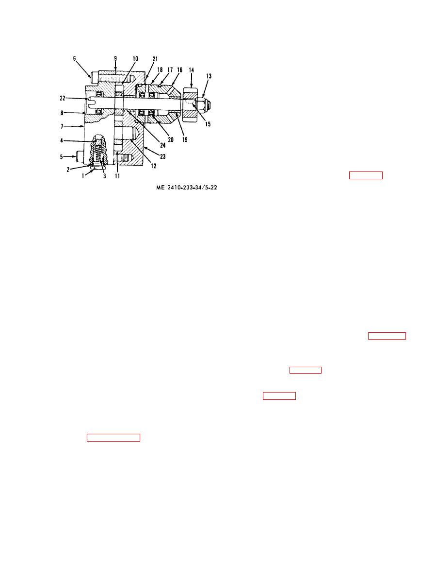 chips, nicks, and other damage. Check for cracks
and rough spots at the mating surface. Repair or
replace as required.
(2) Inspect the spring for cracks and weak
condition. Replace if necessary.
(3) Inspect the gears for chipped or broken
teeth and for wear. Repair or replace as required.
(4) Inspect the drive shaft for dents, nicks,
and scratches and for excessive or uneven wear.
Repair surface if possible or replace the shaft.
(5) Inspect the bearings for wear, nicks,
scratches, pitting and other damage.
f. Reassembly. Assemble the pump in the
reverse order o f disassembly. Observe the
following:
(1) Install the bearings so that the tapered
edges are toward seals.
(2) Soak seals (8 and 17, fig. 5-22) in a
solution of 1 part SAE 30 oil to one part diesel fuel
to soften the seals. Tamp the seals firmly into the
pump body bore and around the shaft using a
Nut
13
1
Bolt
tamping tool.
Gear
14
2
Gasket
(3) Install the gear (14) so that the grooved
15
Key
3
Spring
side is out.
Bearing cage
16
4
Plunger
17
Seal
(4) Tighten the nut (13) to a torque of 10
5
Screw
18
Ring
6
Screw
foot-pounds.
19
Bearing
7
Cover
(5) Apply a thin film of sealant to the mating
20
Seal
8
Seal
surfaces of the pump body (23) and cover (7). Do
21
Gasket
9
Gasket
not allow excess sealant to enter the pump.
22
Shaft
10
Gear
g. Installation. Reverse removal procedure and
Body
23
11
Gear
24
Bearing
12
Shaft
install the fuel transfer pump on engine.
5-14. Fuel Tank
(2) Remove the screws (5 and 6) and remove
a. General Refer to TM 5-2410-233-20 for fuel
the cover (7). Remove the seal (8) from the cover.
tank service instructions.
Remove the cover mounting gasket (9).
b. Removal.
(3) Remove the gear (10) from the shaft (22).
(1) Remove guard from tractor (fig. 5-23).
Remove the gear (11) and shaft (12).
(2) Close fuel shutoff and remove the fuel
(4) Remove the nut (13). Pull the gear (14)
supply and drain lines at the tank.
from the shaft and remove the key (15).
(3) Remove the seat (TM 5-2410-233-20)
(5) Remove the bearing cage (16). Remove
and seat frame (para 2-9).
the seal (17), ring (18) and the bearing (19).
(4) Disconnect fuel tank ground wire located
Remove the gasket (21).
on fuel tank just behind right rear corner of seat
(6) Remove the shaft (22) from the body
support (fig. 2-33, sheet 1).
(23). Press out the bearing (24).
(5) Remove bolt, wire clip, and pull light wire
d. Cleaning. Clean all components except
away from fuel tank.
bearings with cleaning solvent (Fed. Spec P-D-680)
(6) Remove 4 fuel tank mounting bolts.
and dry with compressed air. Clean bearings as
(7) Pass a chain through each of the two
instructed in paragraph 2-6.
passageways in the tank. Attach chain ends to a
e. Inspection and Repair.
hoist and remove fuel tank from tractor.
(1) inspect the cover and housing for cracks,
|
|
Privacy Statement - Press Release - Copyright Information. - Contact Us |
