 |
|||
|
|
|||
|
|
|||
| ||||||||||
|
|
 TM 9-2320-364-34-1
Remove all jewelry such as rings, dog tags,
bracelets, etc. If jewelry or tools contact
positive electrical circuits a direct short
may result. Damage to equipment, injury or
death to personnel may result.
Do not stand under crane. Mechanical failure
and operator error can cause injury or death
to personnel.
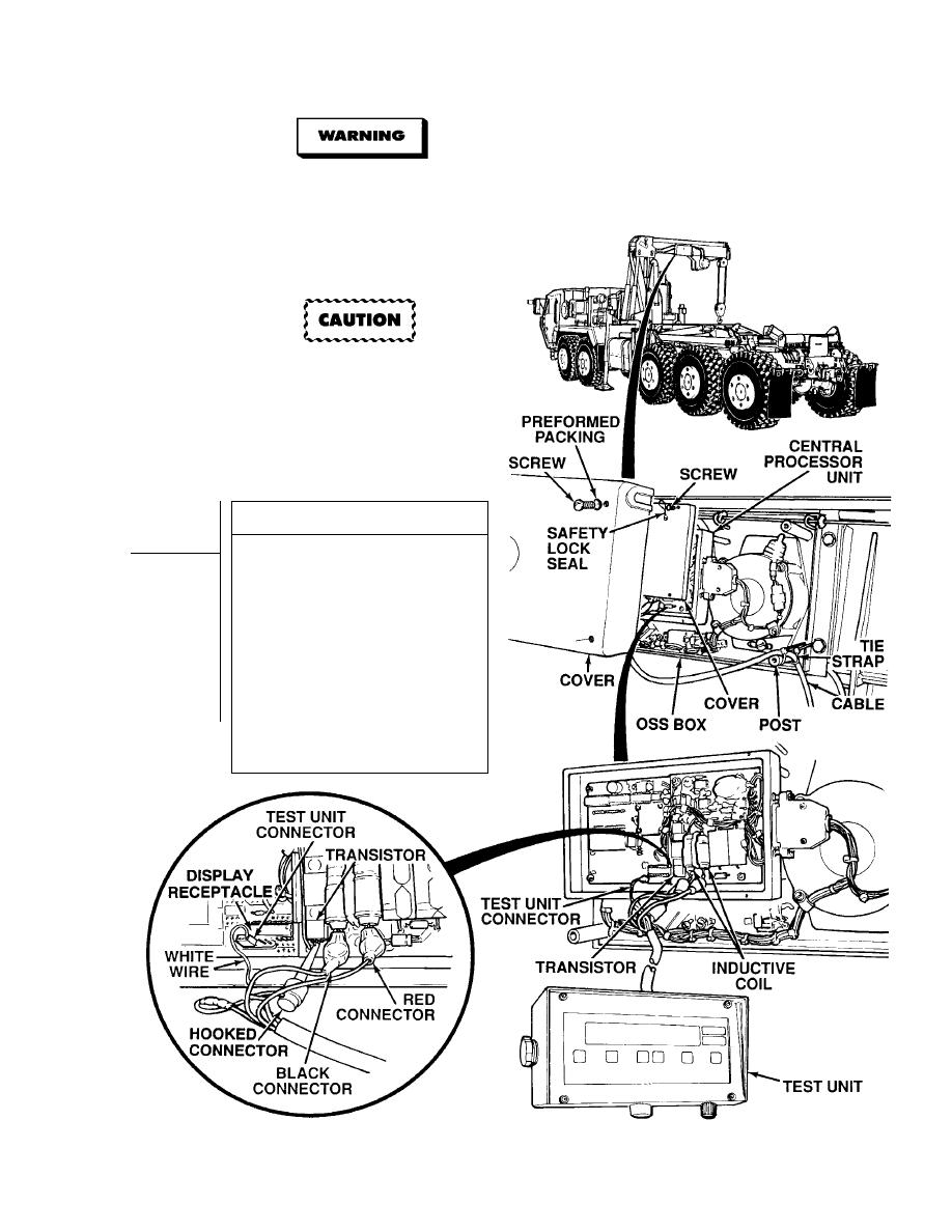
Hooked test unit connector must not
contact other transistor wire or damage
to OSS and test unit will result.
NOTE
When connecting test unit connector to display
receptacle, test unit connector white wire
receptacle must be engaged in the third pin
from the right (fourth pin from left) of display
receptacle.
CALIBRATION TEST
(1) Remove four screws, preformed
packings, and cover from OSS box.
Discard preformed packings.
(2) Remove safety lock seal from two
screws.
(3) Remove four screws and cover from
central processor unit.
(4) Connect test unit connector to display
receptacle pins.
(5) Connect test unit red connector to
RH inductive coil wire.
(6) Connect test unit black connector to
LH inductive coil wire.
(7) Connect test unit hooked connector to
transistor middle wire.
Continued on next page.
|
|
Privacy Statement - Press Release - Copyright Information. - Contact Us |
