 |
|||
|
|
|||
|
|
|||
| ||||||||||
|
|
 TM 9-2320-364-20-1
Allow engine to cool before performing
troubleshooting maintenance. If necessary
use insulated pads and gloves. Hot engine
components will burn and cause injury to
personnel.
Remove all jewelry such as rings, dog tags,
bracelets, etc. If jewelry or tools contact
positive electrical circuits, a direct short
may result. Damage to equipment, injury or
death to personnel may occur.
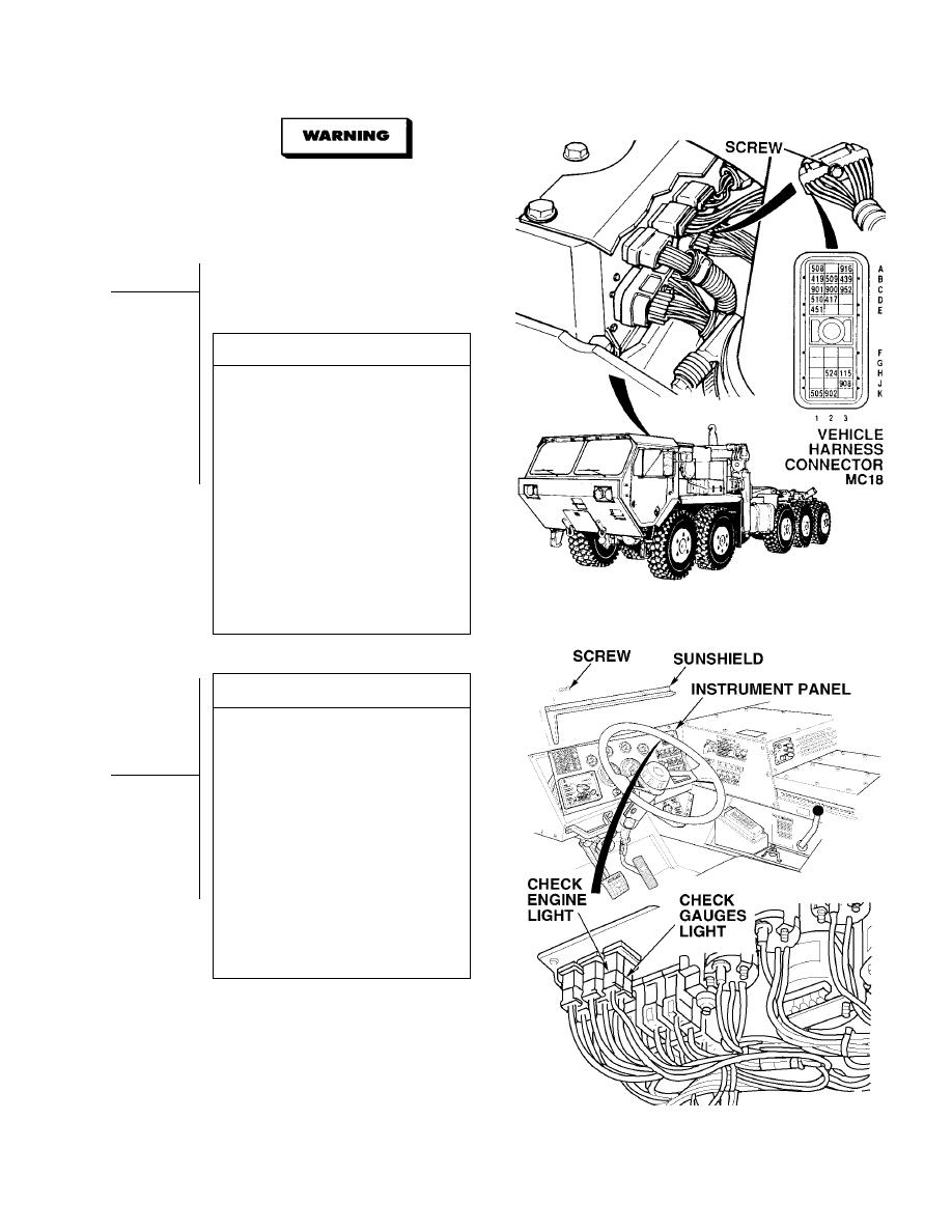
VOLTAGE TEST
(1) Set multimeter select switch to
volts dc.
(2) Turn ON ENGINE switch
(TM 9-2320-364-10).
(3) Are there 10 to 14 vdc present
between wire 439 at vehicle harness
connector MC18, terminal B3 and a
known good ground?
(a) If less than 10 to 14 vdc are not
present, turn OFF ENGINE switch
and repair wire 439 (see
schematic Fig 2-1) or notify DS
Maintenance.
(b) If 10 to 14 vdc are present,
turn OFF ENGINE switch and go
to Step 3 of this Fault.
(4) Connect vehicle harness connector
MC18 and tighten screw.
CONTINUITY TEST
(1)
Remove ten screws and sunshield
from instrument panel.
(2)
Pull top of instrument panel towards
steering wheel.
(3)
Remove CGL lamp.
(4)
Set multimeter select switch to
ohms.
(5)
Is continuity measured across CGL
lamp?
(a) If there is no continuity, replace
lamp (Para 7-24).
(b) If there is continuity, lamp is OK.
Repair wire 509 (see schematic
Fig 2-1) or notify DS
Maintenance.
(6)
Install instrument panel and
sunshield with ten screws.
(7)
Close top engine access cover.
|
|
Privacy Statement - Press Release - Copyright Information. - Contact Us |
