 |
|||
|
|
|||
|
|
|||
| ||||||||||
|
|
 TM 9-2320-364-20-1
Allow engine to cool before performing troubleshooting maintenance. If necessary use insulated pads
and gloves. Hot engine components will burn and cause injury to personnel.
Remove all jewelry such as rings, dog tags, bracelets, etc. If jewelry or tools contact positive electrical
circuits, a direct short may result. Damage to equipment, injury or death to personnel may occur.
DDEC ECM connector terminals are easily
damaged. Use care when connecting and
disconnecting connectors.
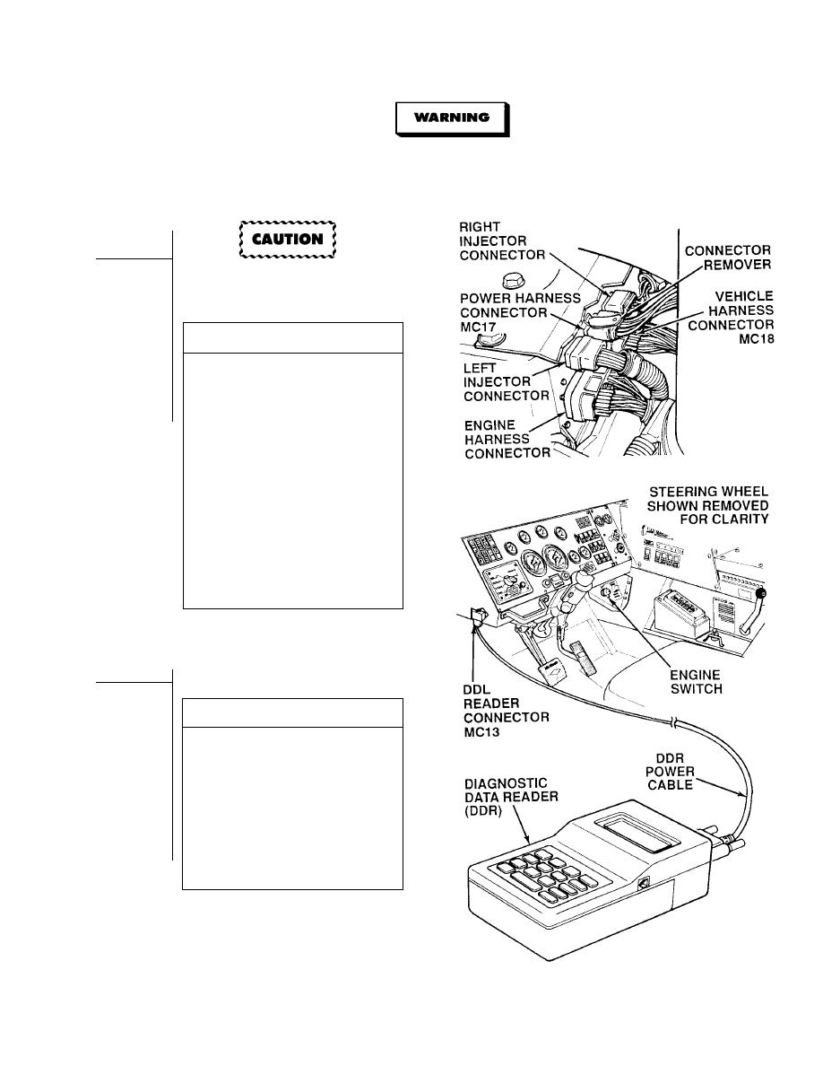
VISUAL INSPECTION
(1) Disconnect all connectors at
DDEC ECM (Para 7-56).
(2) Check all terminals at harness
connectors (ECM and harness side)
for damage; bent, corroded and
unseated pins or terminals.
(a) If harness connector(s) is
damaged, repair connector(s)
(Para 7-101) and perform Steps (3)
through (5) below.
(b) If DDEC ECM connector is
damaged, replace DDEC ECM
(Para 7-56).
(c) If harness connector and DDEC
ECM harness connectors are OK,
replace DDEC ECM (Para 7-56).
(3) Connect engine harness connector to
DDEC ECM and tighten screw.
(4) Install heat shield and two screws.
(5) Close top engine access cover.
NOTE
Battery voltage surges, while cranking the
engine, may blank out or reset DDR.
DDR TEST
(1) Select MODE 31 (SRS RECEIVED)
on DDR.
(2) Observe DDR display while cranking
engine (TM 9-2320-364-10).
(a) If SRS received is not displayed in
the DDR, SRS signal is faulty, turn
OFF ENGINE switch and go to
Step 8 of this Fault.
(b) If SRS received is displayed, SRS
signal is OK. Turn OFF ENGINE
switch and go to Step 9 of
this Fault.
|
|
Privacy Statement - Press Release - Copyright Information. - Contact Us |