 |
|||
|
|
|||
|
|
|||
| ||||||||||
|
|
 TM 9-2320-364-20-1
Allow engine to cool before performing trouble-
shooting maintenance. If necessary use insulated
pads and gloves. Hot engine components will
burn and cause personnel injury.
DDEC ECM connector terminals are easily
damaged. Use care when connecting and
disconnecting connectors.
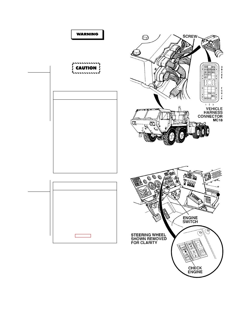
VISUAL INSPECTION
(1) Disconnect all connectors at DDEC
ECM (Para 7-56).
(2) Check terminals at connectors (DDEC
ECM and harness side) for damage;
bent, corroded and unseated pins or
terminals.
(a) If harness connector(s) is
damaged, repair connector
(Para 7-101) and perform Steps
(3) through (5) below.
(b) If DDEC ECM connector is
damaged, replace DDEC ECM
(Para 7-56).
(c) If harness connector DDEC
ECM connectors are OK, replace
DDEC ECM (Para 7-56).
(3) Connect all harness connectors
to DDEC ECM (Para 7-56).
(4) Install heat shield and two screws.
(5) Close top engine access cover.
VERIFY REPAIR
(1) Turn ON ENGINE switch
(TM 9-2320-364-10).
(2) If CEL does not stay ON, start engine
and run for 8 minutes or until CEL
comes ON.
(a) If check engine light comes on for
about five seconds and then goes
off, fault has been corrected.
Perform Step (3) below.
(b) If check engine light comes on
and stays on, perform Step (3)
below and go to Fault
Index (Table 2-16).
(3) Turn OFF ENGINE switch.
|
|
Privacy Statement - Press Release - Copyright Information. - Contact Us |
