 |
|||
|
|
|||
|
|
|||
| ||||||||||
|
|
 TM 9-2320-364-20-1
Remove all jewelry such as rings, dog tags, bracelets, etc. If jewelry or tools contact positive electrical
circuits, a direct short may result. Damage to equipment, injury or death to personnel may occur.
Allow engine to cool before performing troubleshooting maintenance. If necessary use insulated pads
and gloves. Hot engine components will burn and cause personnel injury.
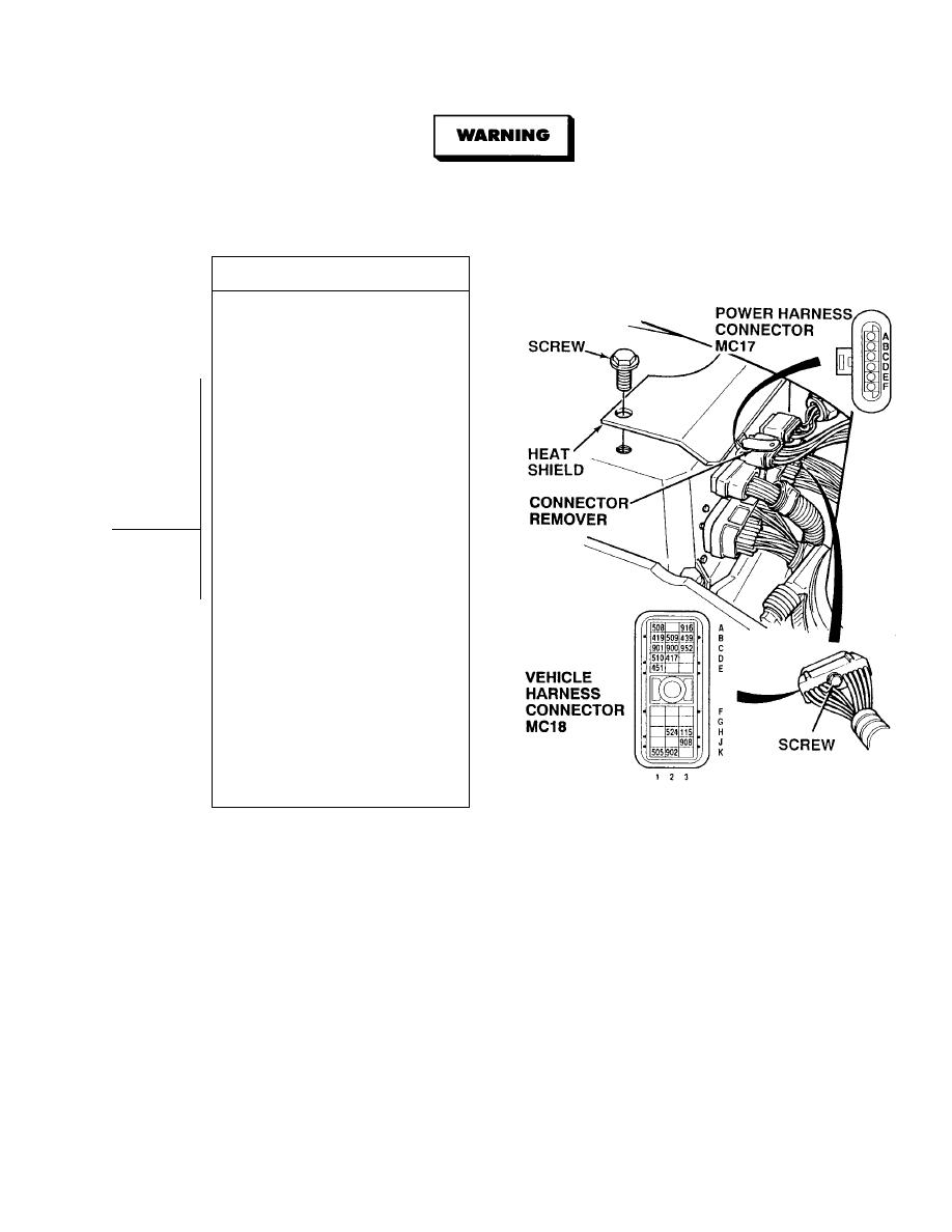
VOLTAGE TEST
(1) Connect positive (+) multimeter lead
to power harness connector MC17,
terminals C.
(2) Connect negative (- ) multimeter lead
-
to terminals A, B, E and F.
(3) Turn ON ENGINE switch
(TM 9-2320-364-10).
(4) Are there more than 10 to 14 vdc
present between wire 150 at power
harness connector MC17, terminal C
and wires 241 and 240 at terminals A,
B, E and F one at a time?
(a) If there are less than 10 vdc
present, repair wire 150 (see
schematic Fig 2-3) or notify DS
Maintenance and perform Steps
(6) and (7) below.
(b) If there are 10 to 14 vdc present,
go to Step (5) below.
(5) Are there less than 10 vdc present
between wire 150 at power harness
connector MC17, terminal D and
wires 241 and 240 at terminals A,
B, E and F?
(a) If there are less than 10 vdc
present, repair wire 150 (see
schematic Fig 2-3) or notify DS
Maintenance and perform Steps
(6) and (7) below.
(b) If there are 10 to 14 vdc present,
perform Steps (6) and (7) below
and go to Step 8 of this Fault.
(6) Connect power harness
connector MC17.
(7) Install heat shield and two mounting
screws.
|
|
Privacy Statement - Press Release - Copyright Information. - Contact Us |
