 |
|||
|
|
|||
|
|
|||
| ||||||||||
|
|
 TM 9-2320-364-20-1
Allow engine to cool before performing troubleshooting maintenance. If necessary use insulated pads
and gloves. Hot engine components will burn and cause injury to personnel.
Remove all jewelry such as rings, dog tags, bracelets, etc. If jewelry or tools contact positive electrical
circuits, a direct short may result. Damage to equipment, injury or death to personnel may occur.
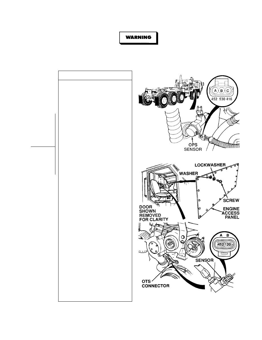
VOLTAGE TEST
(1) Remove 22 screws, lockwashers,
washers and engine access panel.
Discard lockwashers.
(2) Disconnect OPS harness connector.
(3) Connect positive (+) multimeter lead
to OPS harness connector,
terminal A.
(4) Connect negative (- ) multimeter lead
-
OPS harness connector, terminal C.
(5) Turn ON ENGINE switch,
(TM 9-2320-364-10).
(6) Are 4.7 to 5.2 vdc present between
wires 452 and 416 at OPS
connector, terminals A and C?
(a) If less than 4.7 vdc are present,
turn OFF ENGINE switch and go
to Step 5 of this Fault.
(b) If more than 5.2 vdc are present,
go to Step 7 of this Fault.
(c) If 4.7 and 5.2 vdc are present,
OPS connector is OK. Perform
Steps (7) and (8) below.
(7) Turn OFF ENGINE switch.
(8) Connect OPS connector to sensor.
(9) Disconnect OTS harness connector
from sensor.
(10) Connect positive (+) multimeter lead
to OTS harness connector,
terminal A.
(11) Connect negative (- ) multimeter
-
lead OTS harness connector,
terminal B.
(12) Turn ON ENGINE switch,
(TM 9-2320-364-10).
(13) Are 4.7 to 5.2 vdc present between
wires 452 and 120 at OTS
connector, terminals A and B?
(a) If less than 4.7 vdc are present,
turn OFF ENGINE switch,
perform Steps (15) through (17)
below and go to Step 5 of
this Fault.
(b) If more than 5.2 vdc are present,
turn OFF ENGINE switch,
perform Steps (15) through (17)
below and go to Step 7 of
this Fault.
(c) If between 4.7 and 5.2 vdc are
present, OTS connector is OK,
perform Steps (14) through (17)
below.
(14) Turn OFF ENGINE switch.
(15) Connect OPS connector to sensor.
(16) Install engine access panel with 22
washers, lockwashers and screws.
(17) Install right front fender skirt
(Para 17-33).
|
|
Privacy Statement - Press Release - Copyright Information. - Contact Us |
