 |
|||
|
|
|||
|
|
|||
| ||||||||||
|
|
 TM 9-2320-364-20-1
Allow engine to cool before performing troubleshooting maintenance. If necessary use insulated pads
and gloves. Hot engine components will burn and cause injury to personnel.
Remove all jewelry such as rings, dog tags, bracelets, etc. If jewelry or tools contact positive electrical
circuits, a direct short may result. Damage to equipment, injury or death to personnel may occur.
DDEC ECM connector terminals are easily damaged. Use care when connecting and disconnecting
connectors.
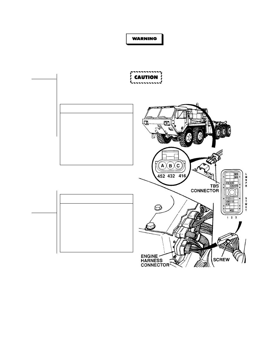
VISUAL INSPECTION
Check terminals at TBS connectors
(sensor side and harness side) for
damage; bent, corroded and
unseated pins or terminals.
(1) If connectors are damaged, repair
connectors (Para 7-101) and
connect TBS harness connector
to sensor connector.
(2) If connectors are free of damage,
replace TBS (Para 7-63) and
connect TBS harness connector
to sensor connector.
RESISTANCE TEST
(1) Loosen screw and disconnect engine
harness connector from DDEC ECM.
(2) Read resistance between wires 416
and 432 at engine harness connector,
terminals W1 and P1.
(a) If 10,000 ohms or less are
present, repair wires 416 and/or
432 (see schematic Fig 2-2) or
notify DS Maintenance.
(b) If more than 10,000 ohms are
present, go to Step 6 of this Fault.
2-269
|
|
Privacy Statement - Press Release - Copyright Information. - Contact Us |
