 |
|||
|
|
|||
|
|
|||
| ||||||||||
|
|
 TM 9-2320-364-20-1
Allow engine to cool before performing
troubleshooting maintenance. If necessary
use insulated pads and gloves. Hot engine
components will burn and cause injury to
personnel.
DDEC ECM connector terminals are easily
damaged. Use care when connecting and
disconnecting connectors.
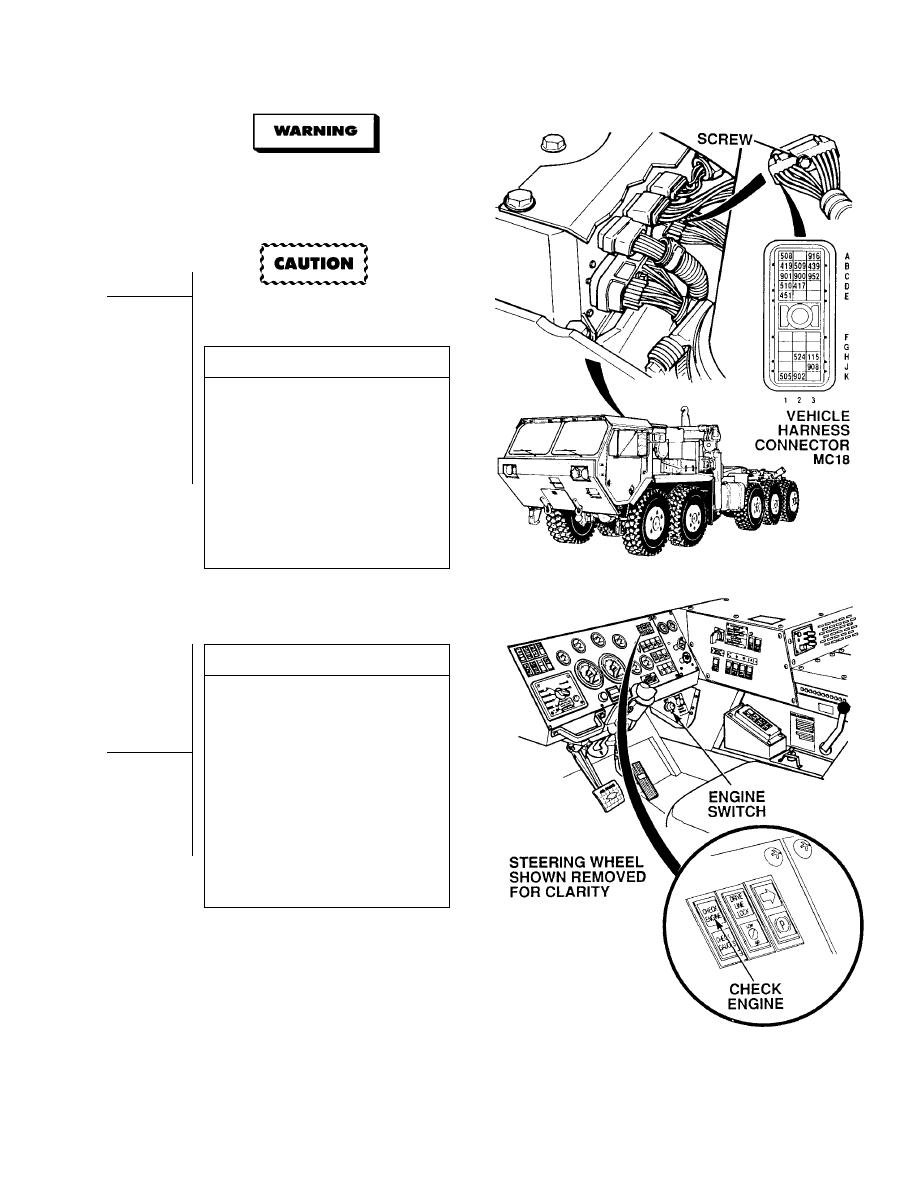
VISUAL INSPECTION
(1) Loosen screw and disconnect vehicle
harness connector MC18 from
DDEC ECM.
(2) Turn ON ENGINE switch
(TM 9-2320-364-10) and
observe CEL.
(a) If CEL stays on, turn OFF
ENGINE switch, and repair
wire 419 (see schematic Fig 2-1)
or notify DS Maintenance.
(b) If CEL goes off after five seconds,
wire 419 is OK.
(3) Turn OFF ENGINE switch.
VISUAL INSPECTION
(1) Check terminals at vehicle harness
connector MC18 (DDEC ECM and
harness side) for damage; bent,
corroded and unseated pins or
terminals.
(a) If harness connector MC18 is
damaged, repair connector
(Para 7-101).
(b) If harness connector MC18 is OK,
replace DDEC ECM (Para 7-56).
(c) If DDEC ECM connector MC18 is
damaged, replace DDEC ECM
(Para 7-56).
(2) Connect vehicle harness connector to
DDEC ECM and tighten screw.
(3) Close top engine cover.
|
|
Privacy Statement - Press Release - Copyright Information. - Contact Us |
