 |
|||
|
|
|||
|
|
|||
| ||||||||||
|
|
 TM 9-2320-364-20-1
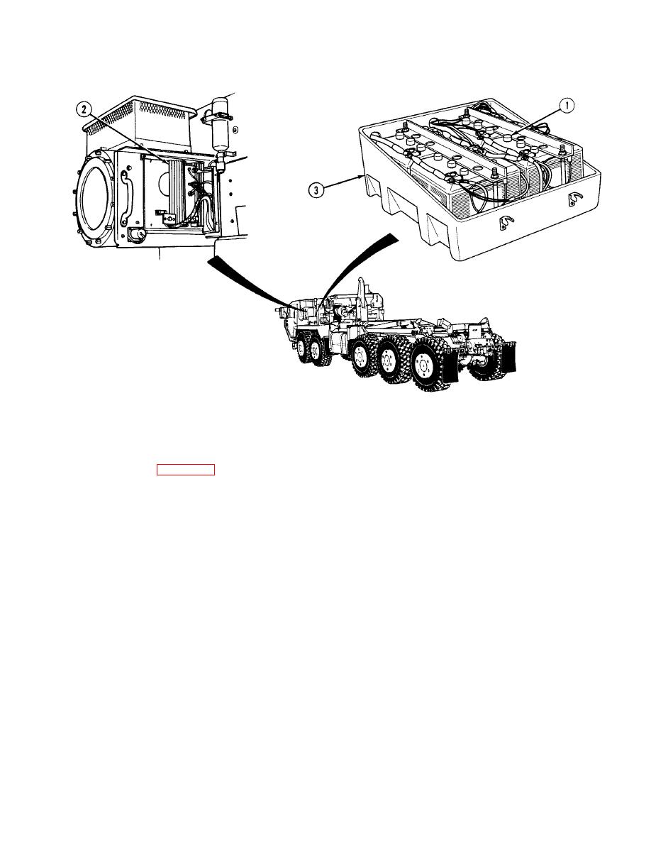
Electrical system (Figure 1-10) power is provided by four 12-volt series-parallel connected batteries (1). PLS trucks
are either equipped with the dual voltage control system (DUVAC) and a 145 AMP alternator or the polarity
protection system and a 200 AMP alternator. The DUVAC (2) delivers up to full alternator output on demand to either
the 24 volt load, 12 volt load, or any combined load requirement from a single alternator. The DUVAC system can
maintain battery equalization and balance even when the batteries are not matched or when they are in different
charge states. Separate voltage regulation is provided for each battery bank. The battery box (3) is located on the
left-hand fender and vents to the truck exterior. This location provides protection from the environment and allows
ready access for service. The fiberglass battery box cover is designed to prevent short circuits during maintenance
and operation. Power is distributed throughout the truck by wiring harnesses. The harnesses are interconnected by
pin connectors. Connectors are provided at the rear of the truck to supply power for towed loads.
1-13
|
|
Privacy Statement - Press Release - Copyright Information. - Contact Us |
