 |
|||
|
|
|||
|
Page Title:
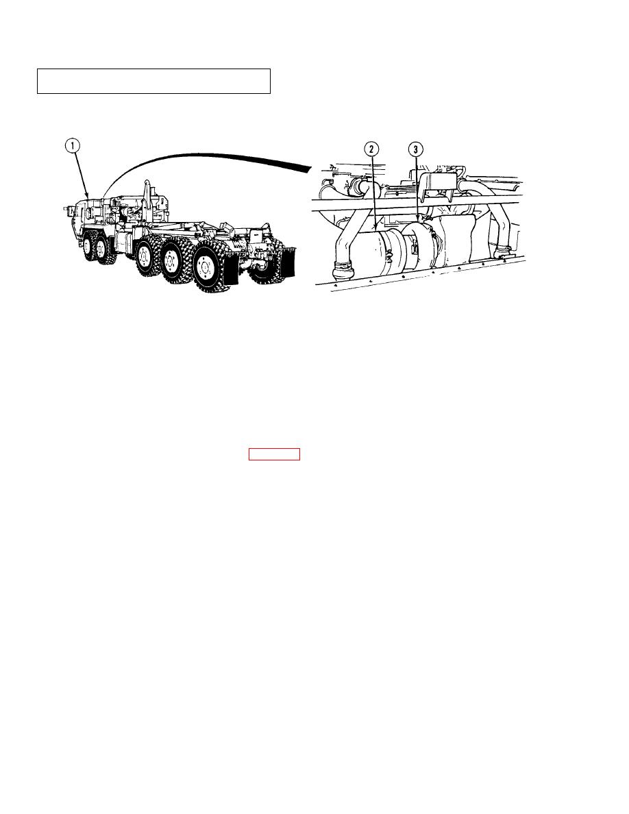
Figure 1-7. Air Intake System |
|
||
| ||||||||||
|
|
 TM 9-2320-364-20-1
1-11. ENGINE SYSTEMS (CONT).
b. Air Intake System. The air intake system (Figure 1-7) consists of a dry-type air cleaner (1), ducting (2),
turbocharger (3) and engine blower. Engine exhaust gases flow through the turbocharger driving a turbine
wheel. A compressor wheel on the opposite end of the turbine wheel shaft rotates and draws in fresh air through
the air cleaner, compresses the air and delivers it to the engine blower.
1-10
|
|
Privacy Statement - Press Release - Copyright Information. - Contact Us |