 |
|||
|
|
|||
|
|
|||
| ||||||||||
|
|
 TM 9-2320-360-34-2
27-6. GEAR REDUCER REPAIR
This task covers:
a. Disassembly
c. Assembly
b. Cleaning/Inspection
d. Follow-On Maintenance
INITIAL SETUP
Equipment Conditions
Materials/Parts
Gear reducer removed (TM 9-2320-360-20).
Adhesive-Sealant (Item 3, Appendix B)
Adhesive-Sealant (Item 6, Appendix B)
Tools and Special Tools
Adhesive-Sealant, Permatex No. 1
Tool Kit, Genl Mech (Item 202, Appendix E)
(Item 9, Appendix B)
Pan, Oil Drain (Item 102, Appendix E)
Cloth, Crocus (Item 16, Appendix B)
Press, Hydraulic (Item 116, Appendix E)
Compound, Sealing, Pipe Thread (Item 28,
Puller Kit, Mechanical (Item 124, Appendix E)
Solvent, Dry Cleaning (Item 54, Appendix B)
Tags, Identification (Item 56, Appendix B)
Repair Kit (Item 228.1, Appendix F)
a. Disassembly
NOTE
Tag and mark housing
before
disassembly.
(1)
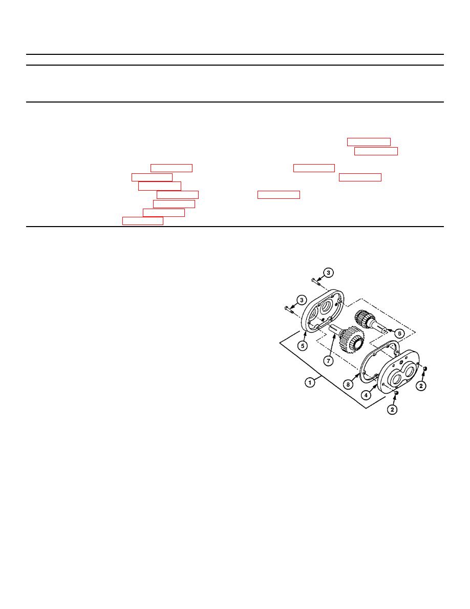
Position drain pan under gear reducer (1).
CAUTION
During separation of housing, do not
allow gears to fall.
Damage to
equipment may result.
NOTE
Output housing has three pipe plugs,
Input housing has one pipe plug.
(2) Remove two nuts (2), screws (3), and input
housing (4) from output housing (5).
(3) Remove input shaft (6) from input housing (4).
(4) Remove output shaft (7) from output housing
(5).
(5) Remove gasket(s) (8) from housing (4 or
5).Discard gasket(s).
27-52
|
|
Privacy Statement - Press Release - Copyright Information. - Contact Us |