 |
|||
|
|
|||
|
|
|||
| ||||||||||
|
|
 TM 9-2320-360-34-2
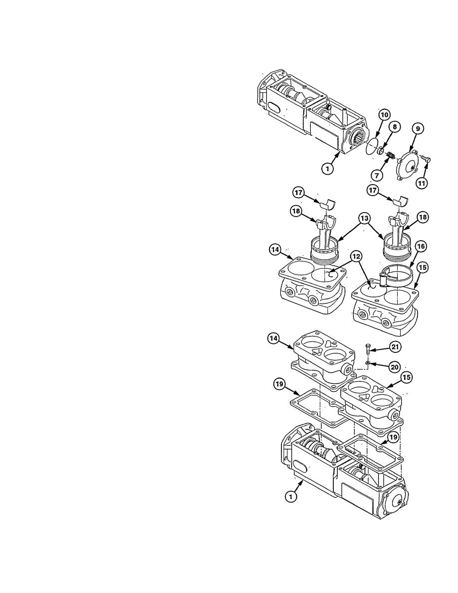
(5) Install spring (7) and oil flow regulator (8)
in bearing end cover (9).
(6) Install new preformed packing (10) in
bearing end cover (9).
NOTE
When properly installed, tab on oil
flow regulator should be up.
(7) Install bearing end cover (9) on crankcase
assembly (1) with four screws (11).
(8) Coat cylinder walls (12) and piston and
rod assemblies (13) with lubricating oil.
(9) Install four piston and rod assemblies (13)
in two cylinder blocks (14 and 15) using
piston ring compressor (16).
NOTE
Locating tabs on bearing halves must
Insert
in
locating
notches
in
connecting rods.
(10) Install two bearing
halves
(17)
on
connecting rods (18).
(11) Coat two bearing
halves
(17)
with
lubricating oil.
NOTE
Cylinder block should be installed on
crankcase as marked during removal.
(12) Install new gasket (19) and cylinder block
(14) on crankcase assembly (1).
NOTE
Two center screws should be
tightened to 96 lb-in. (11 Nm).
Four outer screws then should be
tightened to 96 lb-in. (11 Nm).
Two center screws then should be
tightened to 27-33 Ib-ft (37-45
Nm).
Four outer screw s then should be
tightened to 27-33 Ib-ft (37-45
Nm).
(13) Install six new lockwashers (20) and
screws (21) on cylinder block (14).
Torque to 27-33 lb-ft (37-45 Nm).
(14) Repeat steps (10) thru (13) for cylinder
block (15).
26-9
|
|
Privacy Statement - Press Release - Copyright Information. - Contact Us |