 |
|||
|
|
|||
|
|
|||
| ||||||||||
|
|
 TM 9-2320-360-34-2
26-2. AIR COMPRESSOR REPAIR (CONT)
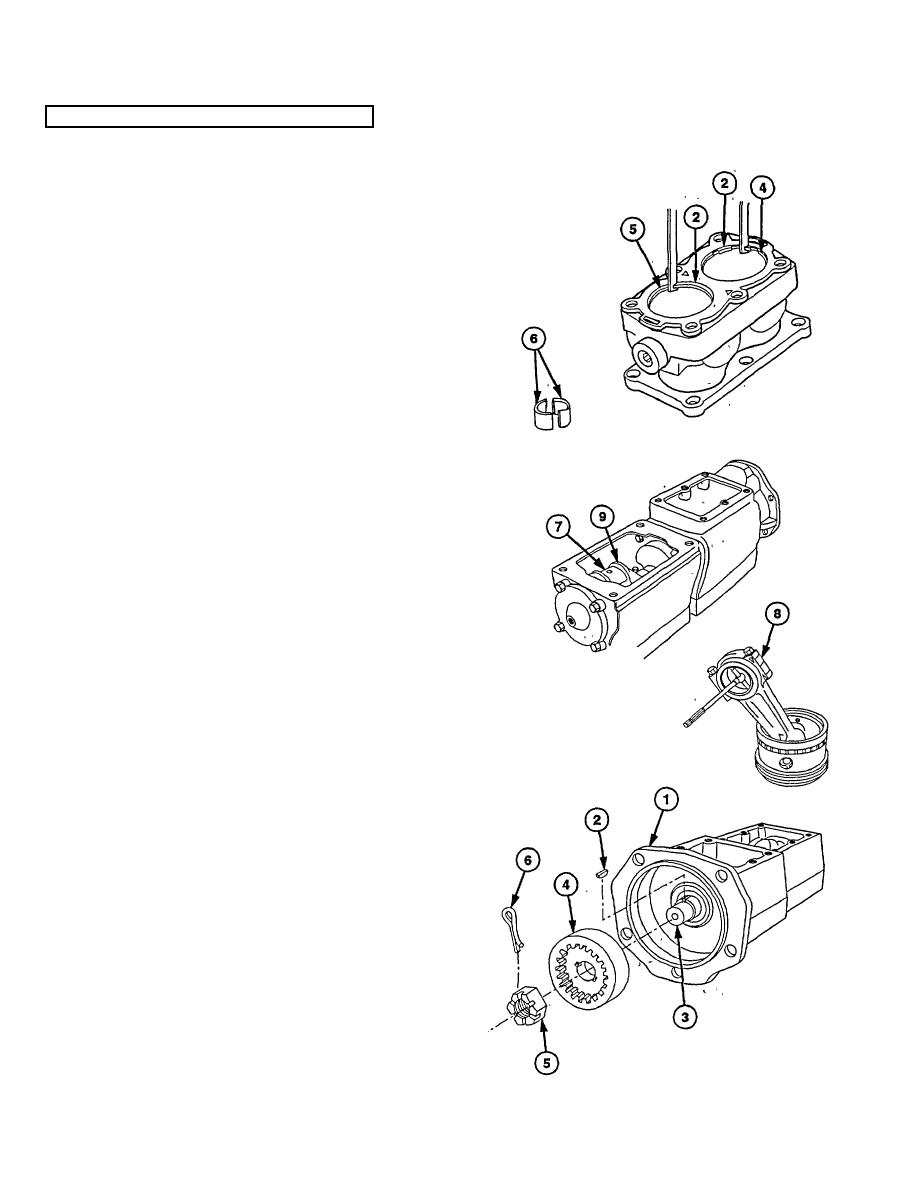
(13) Position compression ring (4) in cylinder
bore (2) and measure end gap clearance.
Replace rings if clearance exceeds 0.017
in. (0.43 mm).
(14) Position oil ring (5) in cylinder bore (2) and
measure end gap clearance. Replace
rings if clearance exceeds 0.055 in. (1.40
mm).
(15) Inspect connecting rod bearings (6) for
scoring, pitting, or visible wear. Clearance
between bearings (6) and crankshaft
journals (7) must be 0.005-0.0021 in.
(0.053-0.127
mm)
after
assembly.
Replace
bearings
if
clearance
is
exceeded.
(16) Measure distance between side of
connecting rod bearing cap (8) and
crankshaft (9).
Clearance must not
exceed 0.010 in.
(0.254 mm) after
assembly.
Replace connecting rod if
clearance is exceeded.
(17) Check ball bearings for worn or damaged
balls; rotate bearings by hand to detect
roughness. Replace crankcase assembly
if wear, roughness, or damage is evident.
(18) Coat parts with lubricating oil.
c. Assembly
(1) Position crankcase assembly (1) in vise.
(2) Install key (2) in crankshaft (3).
NOTE
When proper torque is reached,
continue to tighten until slot in nut
aligns with hole in crankshaft for
cotter pin.
(3) Install drive coupling (4) and nut (5) on
crankshaft (3). Torque to 80 lb-ft (108
N⋅m).
(4) Install new cotter pin (6) through nut (5)
and crankshaft (3).
26-8
|
|
Privacy Statement - Press Release - Copyright Information. - Contact Us |
