 |
|||
|
|
|||
|
|
|||
| ||||||||||
|
|
 TM 9-2320-360-34-2
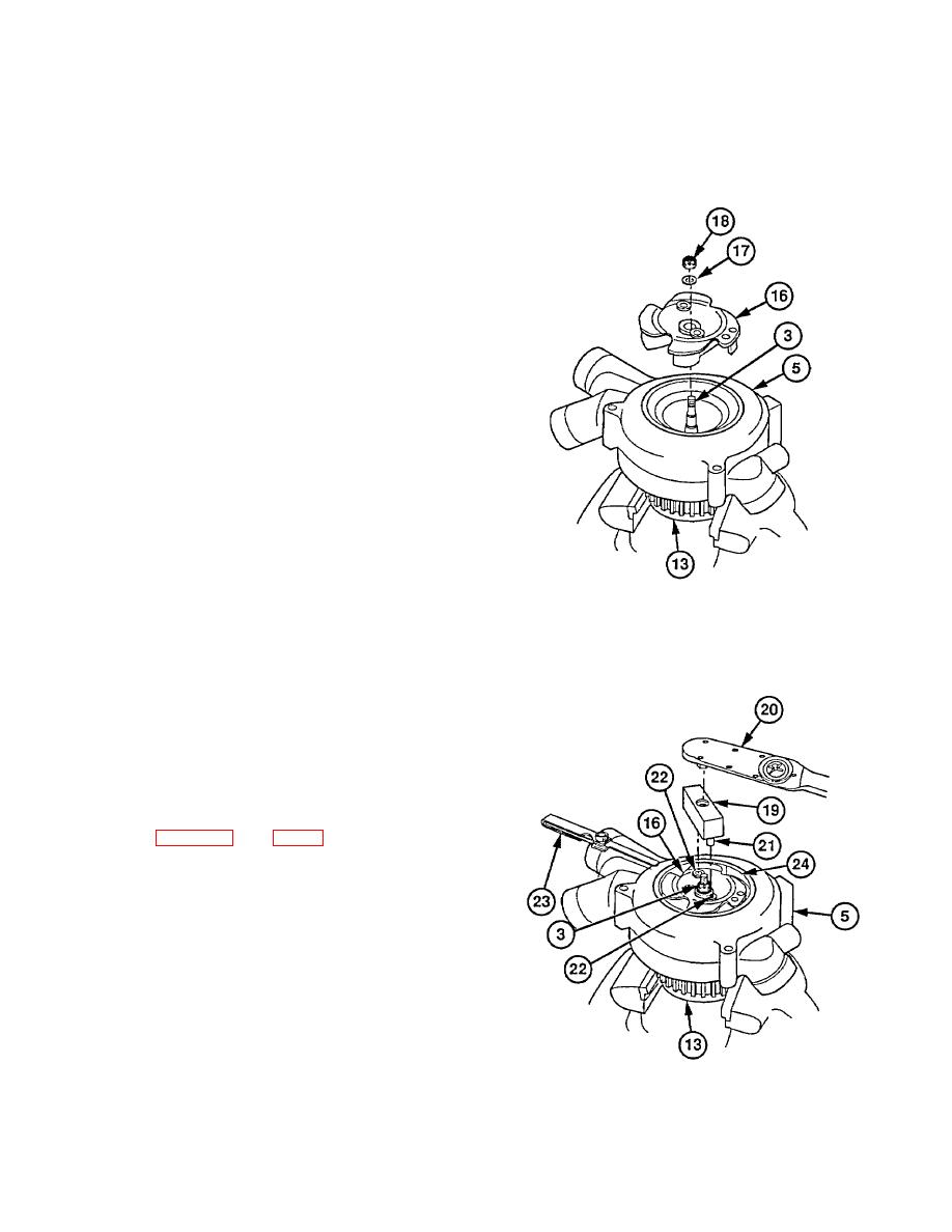
(14) Coat threads of shaft (3) with compound
no. 2.
(15) Place gear (13) in soft-Jawed vise.
(16) Install impeller (16) on shaft (3) with
washer (17) and new locknut (18).
Torque to 35-40 lb-ft (47-54 Nm).
NOTE
Steps (17) thru (21) measure slip
torque of gear.
(17) Scribe a line across gear (13) and shaft
(3).
(18) Scribe a second line across impeller (16),
locknut (18), and shaft (3).
(19) Install ad apter (19) on torque wrench (20).
(20) Insert adapter dowel pins (21) in impeller
puller holes (22) and apply torque of 80
lb-ft (108 Nm). Check assembly for
slippage while applying torque.
NOTE
If slippage was felt, examine scribed
marks to determine if gear or impeller
slipped and do step (21). Otherwise
go to step (22).
(21) Replace shaft (3) and component that
slipped (13 or 16). Repeat steps (17)
thru (20).
(22) Insert 0.015 in. (0.38 mm) feeler gage
(23) through water outlet opening
between impeller (16) and inside wall
(24) of water pump (5).
NOTE
If clearance in step (23) is wrong,
repeat para 21-2a and 21-2b.
(23) Turn impeller (16) while holding feeler
gage (23) in position to check clearance
between all blades of impeller (16) and
inside wall of water pump (5).
(24) Remove gear (13) from vise.
NOTE
Retaining ring, access cover, and
seal ring are installed in para 5-5.
21-7 (21-8 blank)
|
|
Privacy Statement - Press Release - Copyright Information. - Contact Us |
