 |
|||
|
|
|||
|
|
|||
| ||||||||||
|
|
 TM 9-2320-360-34-2
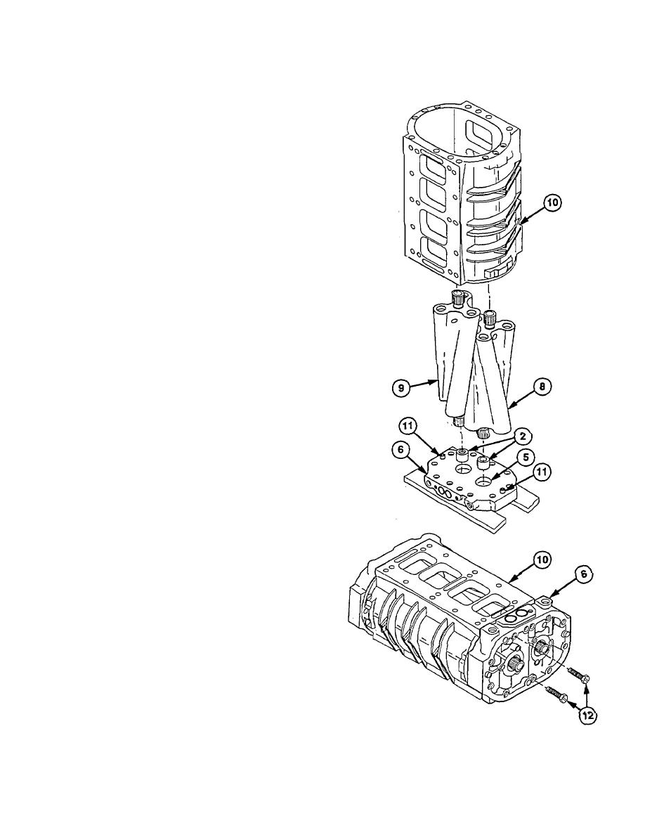
(6) Place front end plate (6) on wooden blocks with
Inner surface up.
(7) Install seal protectors (2), tapered edge down,
on rotors (8 and 9).
NOTE
Seal protectors will drive out
plastic sleeve In seal. Discard
sleeve.
When
properly
installed,
externally splined ends of rotors
will be up, and rotor end with
Internal spline will be in right side
of front end plate.
(8) Align matchmarks made during removal and
install rotors (8 and 9) in bores (5). Work rotors
(8 and 9) until they contact front end plate (6).
CAUTION
Do not let gasket forming compound
protrude into blower housing. Failure
to comply may result In engine
damage.
(9) Lightly coat mating surfaces of blower (10) and
front end plate (6) with gasket forming
compound.
NOTE
Matchmarks made during removal
should be aligned.
(10) Install blower (10) over rotors (8 and 9) until it
contacts dowel pins (11) In front end plate (6).
(11) Align dowel pins (11) with holes in blower (10)
and push blower tight against front end plate (B).
Tap blower (10) with soft-faced hammer If
necessary.
(12) Move blower (10) to work surface while firmly
holding front end plate (6) against blower (10),
Position bottom down.
(13) Install two screws (12) through front end plate
(6) and blower (10).
20-9
|
|
Privacy Statement - Press Release - Copyright Information. - Contact Us |
