 |
|||
|
|
|||
|
|
|||
| ||||||||||
|
|
 TM 9-2320-360-34-2
e. Installation
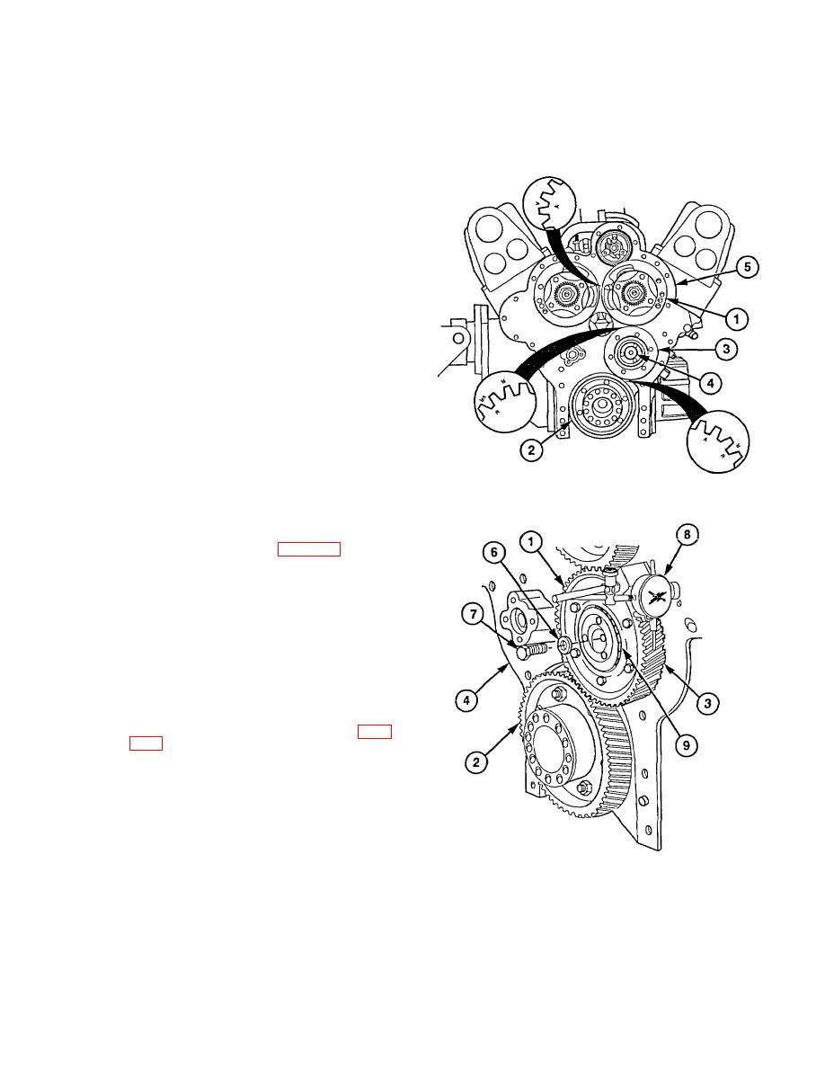
(1) Align timing marks on camshaft gear (1)
and crankshaft gear (2) with timing marks
on idler gear (3).
(2) Slide idler gear (3) in place until
crankshaft gear (2) and camshaft gear (1)
are fully meshed.
(3) Rotate gear hub (4) so dowel in hub aligns
with hole in end plate (5).
(4) Tap hub (4) until it seats against end plate
(5).
(5) Check timing marks again to ensure gears
(1, 2, and 3) are aligned as shown.
(6) Install special washer (6) and screw (7) in
idler gear (3). Torque to 90 lb-ft (122
Nm).
(7) Mount dial indicator (8) on end plate (5)
and check backlash between gears (1, 2,
and 3). Minimum backlash is 0.002 in.
(0.05 mm). Maximum backlash is 0.010
in. (0.25 mm).
(8) Coat bearing (9) and idler gear (3) with
lubricating oil.
f. Follow-On Maintenance
(1) Install flywheel housing (para 19-9).
(2) Install flexplate assembly (para 3-17).
(3) Install oil pan (para 3-20).
(4) Install blower accessory drive hub (para
4-9).
(5) Install 12-volt (rear)
alternator/bracket
(TM 9-2320-360-20).
(6) install DDEC oil
pressure
sensor
(TM 9-2320-360-20).
(7) Remove engine from engine stand (para
(8) Install air box covers (para 3-8).
(9) Install air box drains (para 3-9).
(11) Install 24-volt (front)
alternator/bracket
(TM 9-2320-360-20).
(12) Install
150
amp
circuit
breakers
(TM 9-2320-360-20).
(13) Install starter (TM 9-2320-360-20).
(14) Install sending units and attachments
(TM 9-2320-360-20).
19-119
|
|
Privacy Statement - Press Release - Copyright Information. - Contact Us |