 |
|||
|
|
|||
|
|
|||
| ||||||||||
|
|
 TM 9-2320-360-34-2
19-13. IDLER GEAR REPAIR (CONT)
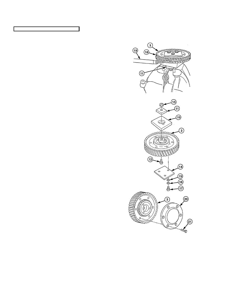
(21) Place plate (11) in jaws of vise.
(22) Install two plastic ties (18) around outside
edge of idler gear (3) and tighten.
(23) Position spring gage (19) hook between
tie strap and idler gear (3).
NOTE
Pull to start gear moving must not
be less than 0.5 lb (0.23 kg) or
more than 4.0 lb (1.8 kg).
If scale reading is more than
specified maximum, rollers are
binding or improperly installed.
If scale reading is less than
specified minimum, bearings are
worn.
(24) Pull spring gage (19) several times and
record pull required to start gear (3)
moving.
Maximum difference between
pulls is 2 lb, 11 oz (1.22 kg).
(25) Remove spring gage (19) and plastic ties
(18) from idler gear (3).
(26) Remove three screws (17), lockwashers
(16), washers (15), and test fixture plate
(14).
(27) Place idler gear assembly (3) in soft-jawed
vise.
(28) Remove nut (13), screw (12), and two test
fixture plates (10 and 11).
(29) Remove idler gear assembly (3) from vise.
(30) Install retainer (20) on idler gear assembly
(3) with six new nylon patch screws (21).
Torque to 30 lb-ft (41 Nm).
19-118
|
|
Privacy Statement - Press Release - Copyright Information. - Contact Us |