 |
|||
|
|
|||
|
Page Title:
ENGINE TO ENGINE STAND INSTALLATION/REMOVAL |
|
||
| ||||||||||
|
|
 TM 9-2320-360-34-2
19-3. ENGINE TO ENGINE STAND INSTALLATION/REMOVAL
This task covers:
a. Installation
c. Follow-On Maintenance
b. Removal
INITIAL SETUP
Equipment Conditions
Tools and Special Tools (Cont)
Sending units and attachments removed
Sling Assemblies (2) (Item 160, Appendix E)
(TM 9-2320-360-20).
Stand, Engine (Item 181, Appendix E)
Starter removed (TM 9-2320-3 60-20).
Wrench, Torque, 0-175 Lb-Ft (Item 236,
150 amp circuit breakers removed
(TM 9-2320-360-20).
24-volt (front) alternator/bracket removed
Materials/Parts
(TM 9-2320-360-20).
Compound, Sealing, Pipe Thread
(Item 28, Appendix B)
Air box drains removed (para 3-9).
Tags, Identification (Item 56, Appendix B)
Air box covers removed (para 3-8).
Ties, Cable, Plastic (Item 60, Appendix B)
Lockwasher (Item 120, Appendix F)
Screws (13) (Item 275, Appendix F)
Tools and Special Tools
Tool Kit, Genl Mech (Item 202, Appendix E)
Plate, Adapter (Item 7, Appendix E)
Personnel Required
Two
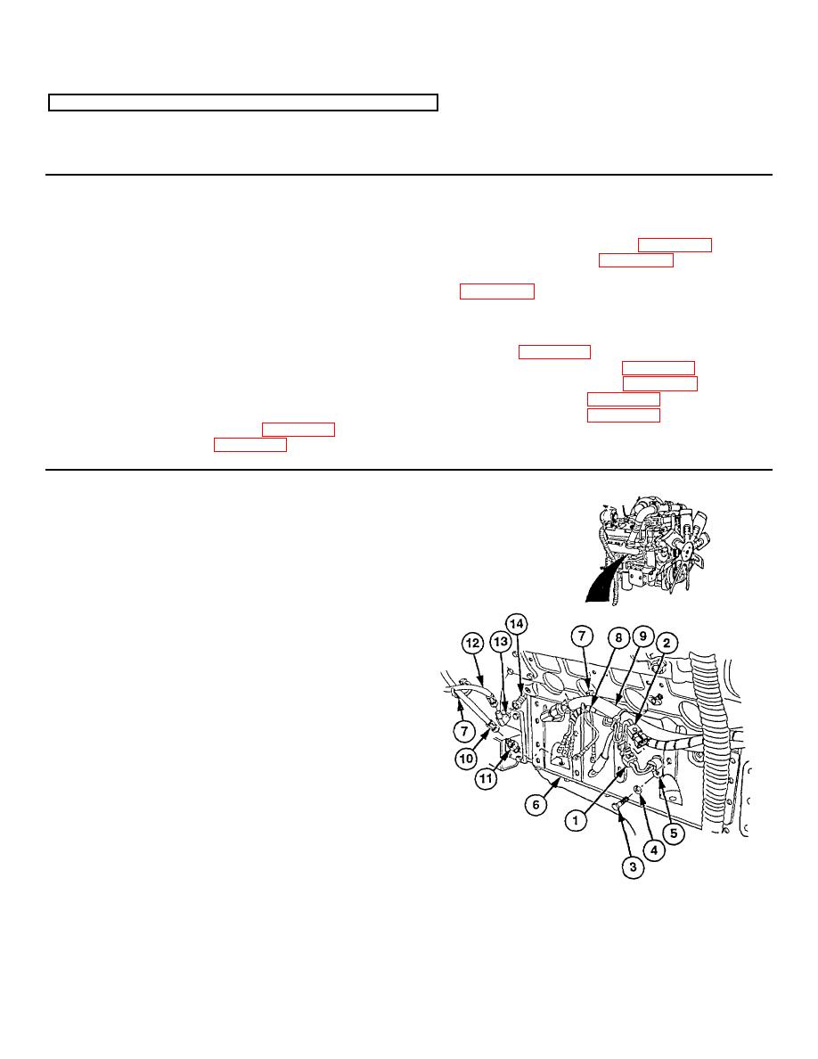
a. Installation
(1) Remove electrical connector (1) from
electrical connector (2).
(2) Remove screw (3), lockwasher (4), and
ether start temperature sensor (5) from
engine assembly (6). Discard lockwasher.
NOTE
Location of plastic cable ties should
be marked before removal.
(3) Remove plastic cable tie (7) from engine
wire harness (8) and hose no. 2630 (9).
(4) Remove hose no. 2761 (10) from adapter
(11).
(5) Remove adapter
(11)
from
engine
assembly (6).
(6) Remove plastic cable tie (7) from hose no.
27 (10) and hose no. 2682 (12).
(7) Remove hose no. 2682 (12) from elbow
(13).
(8) Remove elbow (13) from adapter (14).
(9) Remove adapter
(14)
from
engine
assembly (6).
19-3
|
|
Privacy Statement - Press Release - Copyright Information. - Contact Us |