 |
|||
|
|
|||
|
|
|||
| ||||||||||
|
|
 TM 9-2320-360-34-2
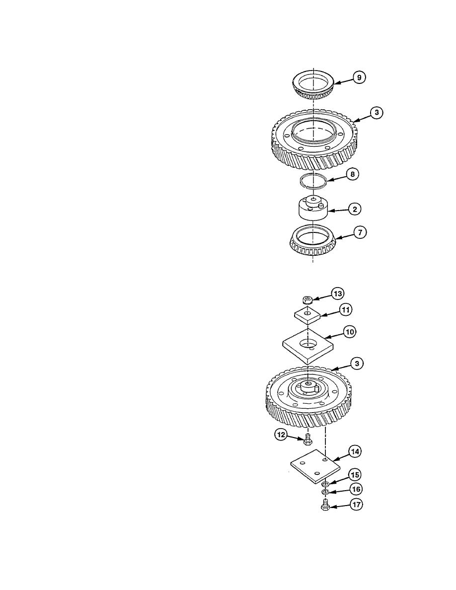
(8) Coat all parts with lubricating oil.
(9) Position outer bearing cone (7), numbered
side down, on bed of press.
(10) Press idler gear hub (2) in outer bearing
cone (7) until bottom of hub (2) Is flush
with bottom of cone (7).
(11) Install inner spacer ring (8) on idler gear
hub (2).
(12) Position gap in spacer ring (8) on side
opposite of oil hole in idler gear hub (2).
(13) Support outer bearing cone (7) and idler
gear hub (2).
(14) Position idler gear assembly (3) on idler
gear hub (2).
(15) Position inner bearing cone (9) on idler
gear assembly (3).
CAUTION
Turn gear while installing bearing
cone on idler gear hub to prevent
damage to bearing cups.
(16) Turn idler gear assembly (3) while
pressing
Inner
bearing
cone
(9),
numbered side up, over hub (2).
(17) Hold hub (2) and turn gear assembly (3) to
see if binding occurs.
NOTE
To check idler gear preload, do steps
(18) thru (28).
(18) Mount idler gear (3) In soft-jawed vise.
CAUTION
Hollow pin on idler gear hub must be
aligned with hole in test fixture plate.
Failure to comply may press pin Into
Idler gear hub.
(19) Mount two test fixture plates (10 and 11)
on idler gear (3) with screw (12) and nut
(13). Torque to 90 Ib-ft (122 Nm).
(20) Mount test fixture plate (14) on idler gear
(3) with three washers (15), lockwashers
(16), and screws (17). Torque to 40 lb-ft
(54 Nm).
19-117
|
|
Privacy Statement - Press Release - Copyright Information. - Contact Us |
