 |
|||
|
|
|||
|
Page Title:
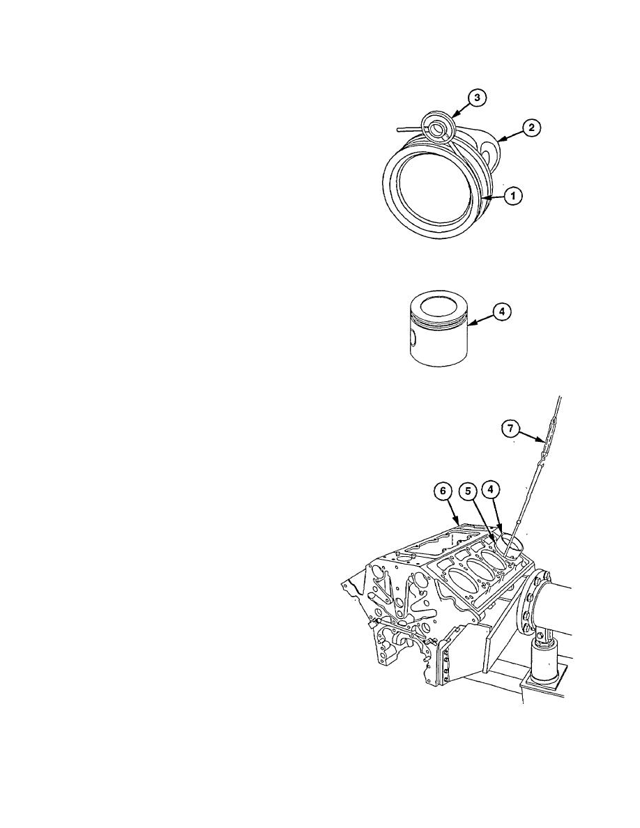
PISTON, CONNECTING ROD, AND LINER REPAIR (cont.) |
|
||
| ||||||||||
|
|
 TM 9-2320-360-34-2
NOTE
Piston crown, bearing, and pin must
be replaced as an assembly.
(6) Slide NO-GO wire of piston groove gaga
tool (3) completely around groove (1). If
wire is below flush at any one area,
replace crown (2).
(7) Slide GO wire of groove gage tool (3)
completely around groove (1).
Wire
should be flush with or slightly higher than
top edge of groove.
(8) Measure diameter of piston skirt (4) and
check for roundness using micrometer.
Diameter must be between 4.8304 and
4.8314 in. (122.69 and 122.72 mm).
NOTE
Piston skirt is installed upside down
in liner.
(9) With cylinder liner (5) installed on engine
block (6), Install piston skirt (4) and feeler
gage in liner (5) at same time. Have
assistant attach piston gage set (7) and
check clearance in four places 90 degrees
apart.
NOTE
Feeler gage size is determined by
amount of wear in piston skirt and
liner.
(10) Select largest feeler gage thickness that
will require a pull of less than 6 lb (2.7 kg).
Clearance will be 0.001 in. (0.25 mm)
greater than feeler gage thickness when it
is withdrawn with a pull of 6 lb (2.7 kg).
Clearance must be between 0.007 and
0.011 in. (0.18 and 0.28 mm).
19-87
|
|
Privacy Statement - Press Release - Copyright Information. - Contact Us |
