 |
|||
|
|
|||
|
|
|||
| ||||||||||
|
|
 TM 9-2320-360-34-2
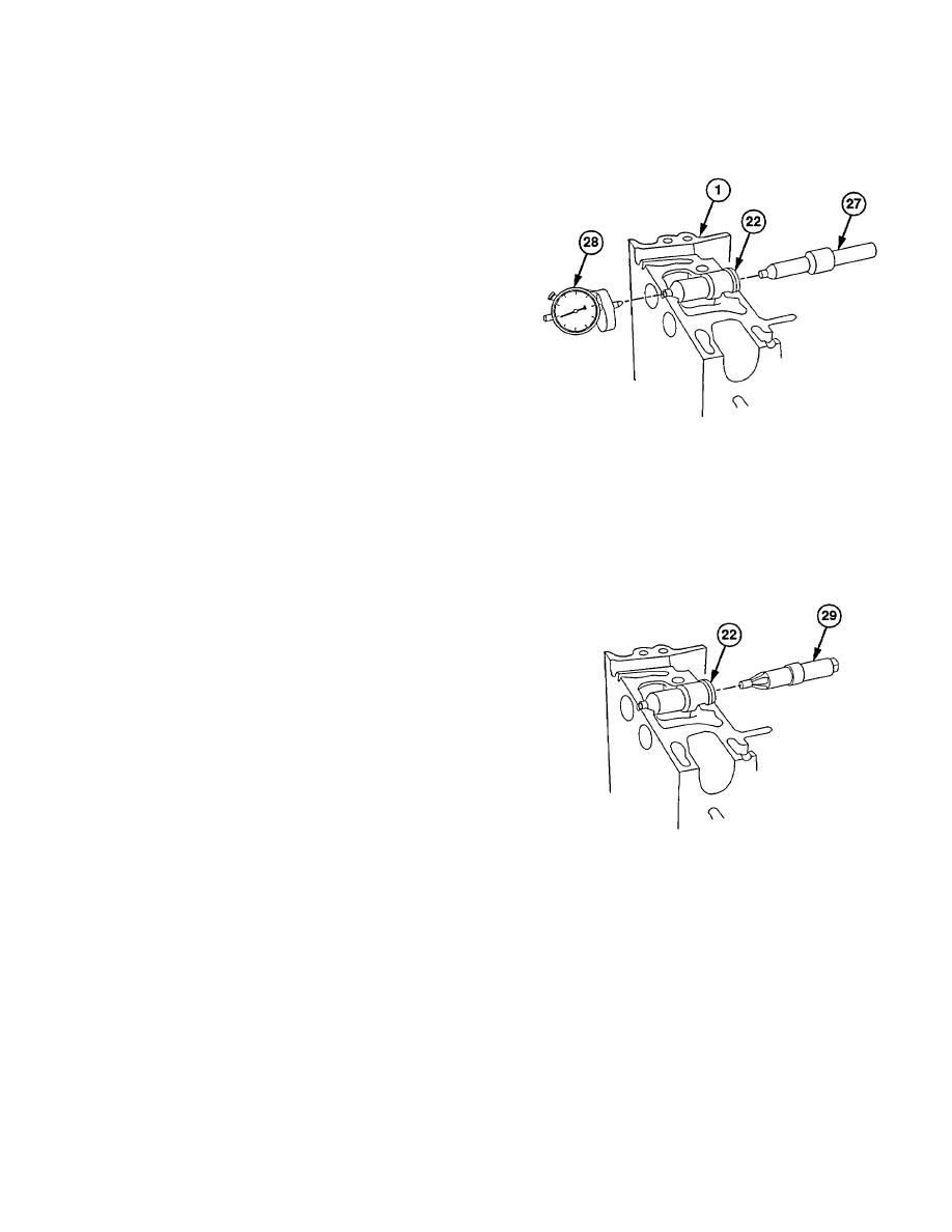
(45) Install injector gage (27) in injector tube (22).
(46) Zero sled gage dial indicator (28) on finished
surface of cylinder head (1).
NOTE
Tip of Injector gage must be flush
with or up to 0.014 in. (0.356 mm)
above or below finished surface of
cylinder head.
If injector gage is more than 0.014
in. above cylinder head surface,
replace injector tube.
If injector gage is more than 0.014
in. below cylinder head surface,
ream injector tube with nut reamer.
Refer to step (48).
(47) Hold Injector gage (27) in injector tube (22) and
move sled gage dial Indicator (28) onto tip of
injector gage (27). Note dial indicator reading
and determine difference from zero reading.
Remove sled gage dial indicator (28) and
injector gage (27).
NOTE
Do step (48) only if nut reaming is
required.
Remove a little metal at a time and
recheck measurement when using
nut reamer.
Always clean out
injector tube before taking a
reading.
(48) Remove excess stock from injector tube (22)
using nut reamer (29).
19-53
|
|
Privacy Statement - Press Release - Copyright Information. - Contact Us |
