 |
|||
|
|
|||
|
|
|||
| ||||||||||
|
|
 TM 9-2320-360-34-2
19-7. CYLINDER HEAD REPAIR (CONT)
(34)
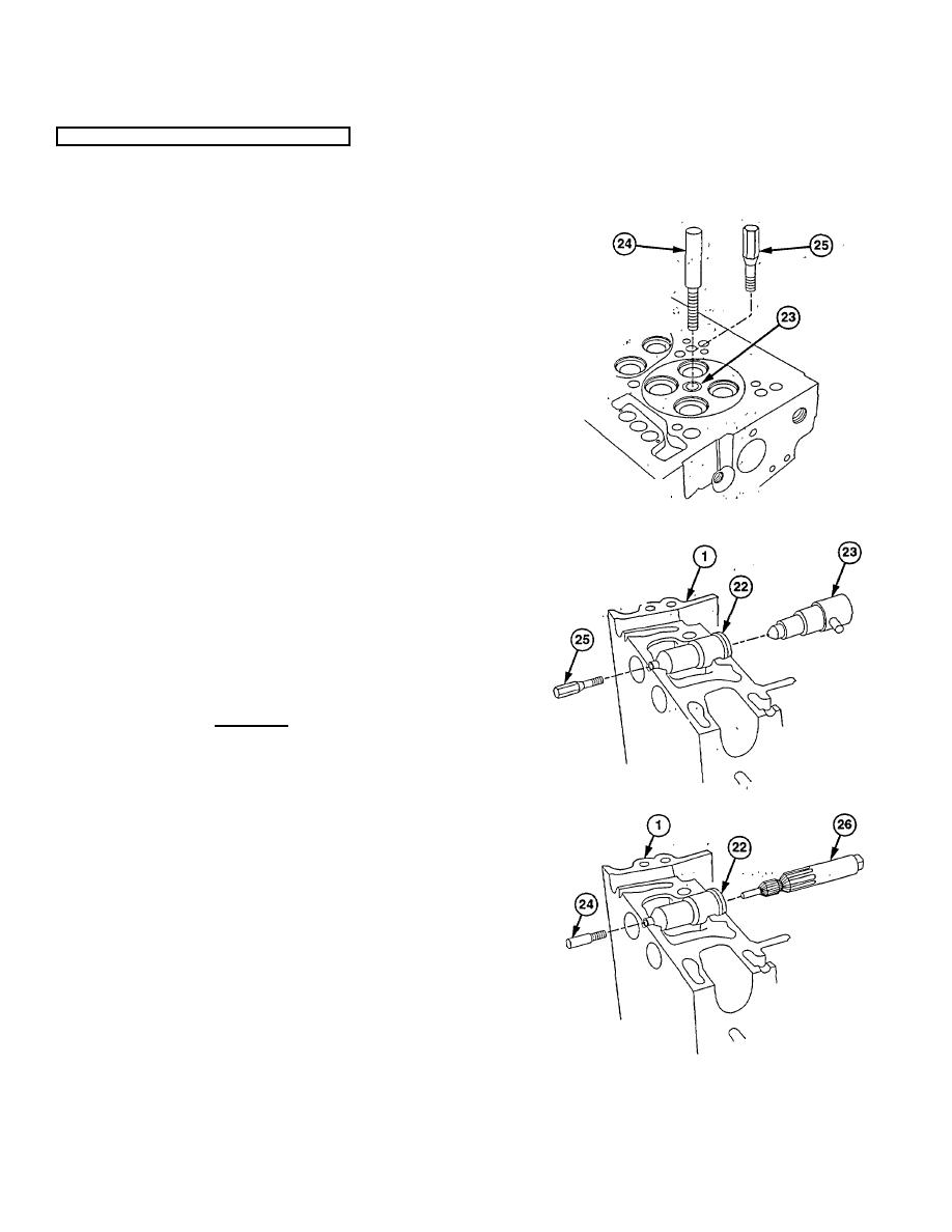
Remove pilot (24) and install upsetting die (25)
in injector tube Installer (23).
(35) Tighten upsetting die (25) to 30 lb-ft (41 Nm) to
flare lower end of injector tube (22).
(36) Remove injector tube installer (23) and upsetting
die (25).
NOTE
Reamer must be turned in clockwise
direction only when inserting and
withdrawing reamer. Movement in
opposite direction will dull cutting
edges.
(37) Place few drops of lubricating oil on cutting edge
of reamer (26) and carefully insert in injector
tube (22).
CAUTION
Ensure all metal chips and shavings
are removed prior to each reaming
operation. Failure to comply may
result in damage to equipment.
(38) Slowly turn reamer (26) clockwise, withdrawing
frequently to remove chips. Continue cutting
until shoulder of cutting edge on reamer (26)
contacts injector tube (22).
WARNING
Compressed
air
for
cleaning
purposes will not exceed 30 psi (207
kPa). Use only with effective chip
guarding and personal protective
equipment (goggles/shield, gloves,
etc.).
(39)
Clean out all metal chips with compressed air.
(40)
Install pilot (24) in reamer (26).
(41)
Place few drops of cutting oil on pilot (24).
(42)
Turn reamer (26) until lower end of injector tube
(22) is flush with or up to 0.005 in. (0.127 mm)
below finished surface on bottom of cylinder
head (1).
(43) Clean out all metal chips with compressed air.
(44) Remove reamer (26) and pilot (24).
19-52
|
|
Privacy Statement - Press Release - Copyright Information. - Contact Us |