|
| |
TM 9-2320-360-34-1
13-8. STEERING SYSTEM ADJUSTMENT (CONT)
(22)
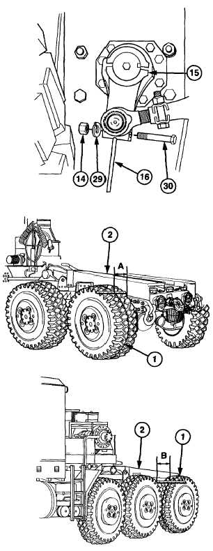
Remove nut (14), lockwasher (29), screw
(30), and steel plate (16) from rear pitman
arm (15). Discard lockwasher.
(23)
Install screw (30), new lockwasher (29),
and nut (14) on rear pitman arm (15).
Torque to 90 lb-ft (122 Nm).
NOTE
If front pitman arm comes in contact
with bumper, repeat steps (13 thru
15) to adjust pitman arm so it does
not come in contact with bumper.
(23)
Start engine (TM 9-2320-360-10) and turn
steering wheel to its full left position to
check front pitman arm.
c.
Drag Link Adjustment
CAUTION
Axles must be positioned straight
ahead
before
continuing
with
alignment procedure. Failure to
comply may result in HET Tractor
dog tracking or excessive tire wear.
NOTE
Axle no. 1 and axle no. 4 are
positioned in the same manner. Axle
no. 4 is shown.
(1)
Measure and record distance A between
rear of left scribe line (1) and left frame
(2).
(2)
Measure and record distance B between
front of left scribe line (1) and left frame
(2).
13-46 Change 2
|