|
| |
TM 9-2320-360-34-1
13-8. STEERING SYSTEM ADJUSTMENT (CONT)
NOTE
·
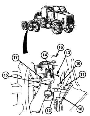
If distances are within specifications, toe-in adjustment is correct. Go to
subpara (b).
·
Axle no. 1 and axle no. 4 tie rods are adjusted in a similar manner. Axle no. 4 is
shown.
·
Left tie rod end has fine threads, right tie rod end has course threads.
(17)
Remove locknut (10) and screw (11) from clamp (12). Discard locknut.
(18)
Remove cotter pin (13) and nut (14) from tie rod end (15) on one side of HET Tractor only using socket
(16). Discard cotter pin.
WARNING
Support tie rod end when removing hardware to prevent it from falling. Failure to
comply may result In Injury.
(19)
Remove tie rod end (15) from steering arm (17).
NOTE
·
Initial distance between tie rod grease fittings should be 61.5 in. (156 cm) for
axle no. 1 and 59.6 in. (151 cm) for axle no. 4.
·
Lengthening axle no. 1 tie rod will decrease front-side measurement;
shortening will increase front-side measurement.
·
Lengthening axle no. 4 tie rod will increase front-side measurement;
shortening will decrease front-side measurement.
(20)
Turn tie rod end (15) counterclockwise to
lengthen or clockwise to shorten tie rod
(18).
(21)
Install screw (11) and new locknut (10) on
clamp (12) to secure tie rod end (15) on
tie rod (18).
(22)
Install tie rod end (15) on steering arm
(17).
(23)
Tighten new locknut (10) on screw (11).
(24)
Install nut (14) on tie rod end (15). Torque
to 165-180 lb-ft (224-244 Nm) using
socket (16).
(25)
Verify adjustment by repeating steps (14)
thru (16).
(26)
Continue tightening nut (14) until hole in
tie rod end (15) aligns with slots in nut
(14).
(27)
Install new cotter pin (13) through nut (14)
and tie rod end (15).
(28)
Repeat steps (17) thru (27) for axle no. 1
(2).
(29)
Manually apply both spring brakes on axle
no. 4 (5) (TM 9-2320-360-10).
13-42
|