Order this information in Print

Order this information on CD-ROM

Download in PDF Format


Click here to make tpub.com your Home Page

Page Title: Installation
Back | Up | Next

Click here for a printed version

Google


Web
www.tpub.com

Home


Information Categories
.... Administration
Advancement
Aerographer
Automotive
Aviation
Combat
Construction
Diving
Draftsman
Engineering
Electronics
Food and Cooking
Math
Medical
Music
Nuclear Fundamentals
Photography
Religion
USMC
   
Products
  Educational CD-ROM's
Printed Manuals
Downloadable Books


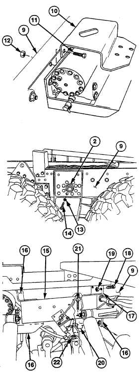
TM 9-2320-360-34-1 (8) Install top left angle bracket  (10)  on  frame (9) with two screws (11) and new locknuts (12).  Do not tighten. (9) Install   eight   new   lockwashers   (13)   and screws (14) in steering gear (2) and frame (9).  Torque to 180 lb-ft (245 Nm). (10) Remove    sling    and    lifting    device    from steering gear (2). NOTE Rear  service  brake  relay  valve  hoses no.      2872   and   no.      2369   must   be routed    between    crossmember    and right side frame. (11) Position  crossmember  (15)  between  three angle brackets (16) with aid of assistant (12) Position  upper  right  angle  bracket  (17)  on frame  (9)  with  two  screws  (18)  and  new locknuts (19).  Do not tighten. (13) Position spacer (20) on crossmember (15) with   four   screws   (21)   and   new   locknuts (22).  Do not tighten. 13-21

Privacy Statement - Press Release - Copyright Information. - Contact Us - Support Integrated Publishing

Integrated Publishing, Inc. - A (SDVOSB) Service Disabled Veteran Owned Small Business