|
| |
TM 9-2320-360-34-1
(5)
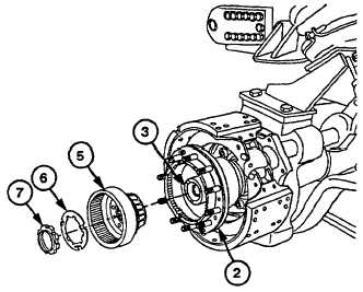
Install ring gear assembly (5) into hub
assembly (2) while assistant lifts hub
assembly (2).
(6)
Install new lockwasher (6) and spindle nut
(7) on spindle assembly (3) with spanner
socket. Tighten nut to 247-290 Ib-ft (335-
393 Nm).
(7)
Rotate hub assembly (2) and torque
spindle nut (7) to 247-290 Ib-ft (335-393
Nm).
CAUTION
Spindle nut must be loosened 1/16
turn. Failure to comply may result in
damage to wheel bearing or spindle.
(8)
Loosen spindle nut (7) 1/16 turn, continue
turning only until tabs on lockwasher (6)
align with slots in spindle nut (7).
CAUTION
· Lockwasher
must
be
properly
positioned on spindle nut shoulder.
Lockwasher must remain loose on
spindle nut when tightening nut. If
lockwasher is not free to move, it is
trapped under the nut and must be
reassembled in the proper position.
Failure to comply may result in
improper wheel bearing preload.
· Two tabs on lockwasher must be
securely bent into notches on spindle
nut. Failure to comply may result in
loss of bearing preload and cause
damage to equipment.
NOTE
· Lockwasher must be loose on
spindle nut.
· Ensure lock tabs do not make
contact with planetary gears.
(9)
Bend two tabs on lockwasher (6) against
spindle nut (7).
(9.1)
Check that spindle nut (7) is secured by
lockwasher (6) and cannot rotate.
Change 1 12-10.1 (12-10.2 blank)
|