|
| |
TM 9-2320-360-34-1
11-4. AXLE NO. 2 AND AXLE NO. 3 BRAKE BRACKET/CAMSHAFT REPAIR
This task covers
a. Removal
d. Assembly
b. Disassembly
e. Installation
c. Cleaning/Inspection
e. Follow-On Maintenance
INITIAL SETUP
Equipment Conditions
Materials/Parts
Wheel hub removed (para 12-3).
Oil, Lubricating (Item 46, Appendix B)
Brake shoes removed (TM 9-2320-360-20).
Locknuts (15) (Item 83, Appendix F)
Slack adjuster removed (TM 9-2320-360-20).
Lockwashers (4) (Item 131, Appendix F)
Seals (3) (Item 287, Appendix F)
Tools and Special Tools
Seal (Item 288, Appendix F)
Tool Kit, Genl Mech (Item 202, Appendix E)
Socket, Sockethead Screw, 14 mm (Item 173,
Appendix E)
Vice, Machinist's (Item 207, Appendix E
Wrench Set, Socket, 3/4 In. Drive (Item 231,
Appendix E)
Wrench, Torque, 0-175 Lb-Ft (Item 236,
Appendix E)
Wrench, Torque, 0-600 Lb-Ft (Item 233,
Appendix E)
a.
Removal
NOTE
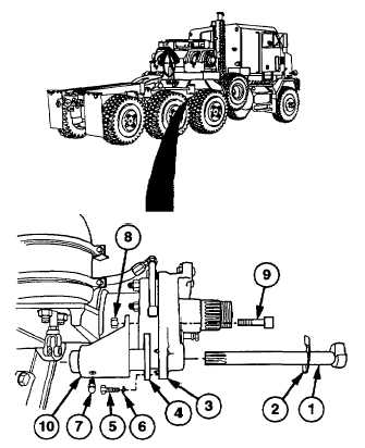
Axle no. 2 and axle no. 3 camshafts
are removed the same way. Axle no.
2 is shown.
(1)
Remove camshaft (1) with thrust washer
(2) from brake bracket (3) and inner
camshaft mounting plate (4).
(2)
Remove four screws (5), lockwashers (6),
and inner camshaft mounting plate (4)
from
brake
bracket
(3).
Discard
lockwashers.
(3)
Remove grease fitting (7) from inner
camshaft mounting plate (4).
(4)
Remove five locknuts (8), screws (9), and
outer camshaft mounting plate (10) from
brake bracket (3). Discard locknuts.
11-8
|