|
| |
TM 9-2320-360-34-1
10-6. AXLE NO. 2, 3, AND 4 OIL SEAL AND YOKE REPLACEMENT
This task covers:
a. Removal
c. Installation
b. Cleaning/Inspection
d. Follow-On Maintenance
INITIAL SETUP
Equipment Conditions
Tools and Special Tools (Cont)
Transfer case in low range
Wrench Set, Socket, 1 In. Drive (Item 230,
(TM 9-2320-360-10).
Appendix E)
Driveline lock-up valve in LOCK position
Wrench, Torque, 0-600 Lb-Ft (Item 233,
(TM 9-2320-360-10).
Appendix E)
Air pressure at 120-125 psi (827-861 kPa).
Propeller shaft removed (table 10-1).
Materials/Parts
Adhesive-Sealant, Silicone (Item 2,
Tools and Special Tools
Appendix B)
Tool Kit, Genl Mech (Item 202, Appendix E)
Oil, Lubricating (Item 48, Appendix B)
Adapter, Socket Wrench, 3/4 In. Female - 1 In.
Nut, Adjusting (4) (2 each Axle No. 2 and No. 3)
Male (Item 6, Appendix E)
(Item 149, Appendix F)
Holder, Yoke (Figure C-15, Appendix C)
Nut, Adjusting (Axle No. 4) (Item 150, Appendix F)
Multiplier, Torque (Item 99, Appendix E)
Seal, Oil (2 each Axle No. 2 and No. 3, 1 each
Puller Kit, Mechanical, Gear and Brg
Axle 4) (Item 305, Appendix F)
(Item 124, Appendix E)
Socket, 55 mm (Item 163.1, Appendix E)
Personnel Required
Socket, 63 mm (Item 163.2, Appendix E)
Two
Table 10-1. Propeller Shaft Removed
Yoke/Seal to be replaced
Propeller Shaft
Axle No. 2 Input
Transfer Case to Axle No. 2
Axle No. 2 Output
Axle No. 2 to Axle No. 3
Axle No. 3 Input
Axle No. 2 to Axle No. 3
Axle No. 3 Output
Axle No. 3 to Axle No. 4
Axle No. 4 Input
Axle No. 3 to Axle No. 4
a.
Removal
NOTE
All seals and yokes on axles no. 2,
no. 3, and no. 4 are replaced in the
same manner. No. 4 axle is shown.
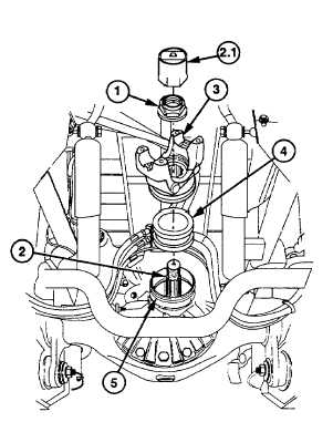
(1)
Unstake and remove locknut (1) from
shaft
(2)
using yoke holder and socket (2.1) with
aid of assistant. Discard locknut.
(2)
Remove yoke (3) from shaft (2).
(3)
Remove oil seal (4) from housing (5).
Discard seal.
Change 1 10-37
|