|
| |
TM 9-2320-360-34-1
10-5. AXLE ALIGNMENT (CONT)
NOTE
Lowering axle will aid in installing or
removing spacers.
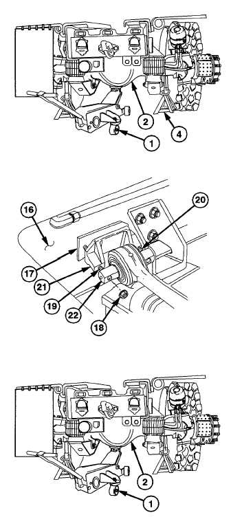
(17)
Raise
floor
jack
(1)
and
remove
jackstands (4).
(18)
Lower differential (2) with floor jack (1) to
add or remove spacers (17).
(19)
Remove two locknuts (18), screw (19),
screw (20), spacers (17), bracket (21),
and torque rod (22) from left frame rail
(16). Discard locknuts.
NOTE
Spacer thickness is 0.125 in. (3.15
mm). Do not use more than six
spacers.
(20)
Add
or
remove
spacers
(1
7)
so
measurements in steps (15) and (16) are
equal to or less than 0.125 in. (3.18 mm)
difference.
(21)
Install bracket (21), torque rod (22),
spacers (17), screw (19), screw (20), and
two new locknuts (18) on left frame rail
(16) with aid of assistant. Torque to 212
lb-ft (287 Nm).
NOTE
Axle must be returned to 9 in. (23 cm)
ride height before doing step (22).
(22)
Repeat steps (9) thru (16).
(23)
Lower floor jack (1) and remove from
differential (2).
b.
Follow-On Maintenance
(1)
Install
input
propeller
shaft
(TM 9-2320-360-20).
(2)
Install wheels/tires (TM 9-2320-360-20).
10-36
|