|
| |
TM 9-2320-360-34-1
10-5. AXLE ALIGNMENT (CONT)
NOTE
Front of differential can be supported
with floor jack to aid in removal or
installation of spacers.
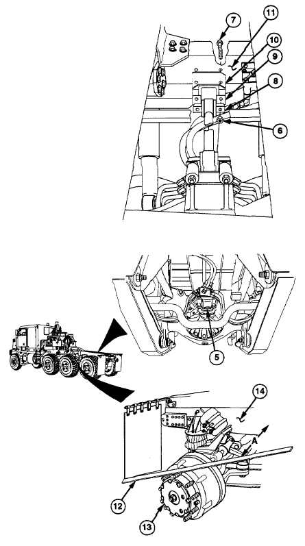
(5)
Remove two locknuts (6), screws (7),
longitudinal torque rod (8), bracket (9),
and spacers (10) from crossmember (11).
Discard locknuts.
NOTE
·
Spacer thickness is 0.125 in. (3.15
mm). Do not use more than six
spacers.
·
Adding one spacer will increase
driveline angle by approximately
1 degree. Removing one spacer
will decrease driveline angle by
approximately 1 degree.
(6)
Add or remove spacer(s) (10) to change
driveline angle.
(7)
Install spacers (10), bracket (9), and
longitudinal
torque
rod
(8)
on
crossmember (11) with two screws (7) and
new locknuts (6).
(8)
Position combination square on yoke (5)
to recheck driveline angle.
NOTE
Axle no. 4 should be positioned
straight ahead.
(9)
Place straightedge (12) against machine-
surfaced outer edge of right brake drum
(13).
(10)
Measure and record distance A between
front of straightedge (12) and right frame
rail (14).
10-34
|