|
| |
TM 9-2320-360-34-1
10-5. AXLE ALIGNMENT
This task covers:
a. Alignment
b. Follow-On Maintenance
INITIAL SETUP
Equipment Conditions
Tools and Special Tools (Cont)
Wheels/tires removed from affected axle
Tape, Measuring (Item 188, Appendix E)
(TM 9-2320-360-20).
Wrench, Torque, 0-600 Lb-Ft (Item 233,
Input propeller shaft removed from affected
Appendix E)
axle (TM 9-2320-360-20).
Materials/Parts
Tools and Special Tools
Locknuts (4) (Item 87, Appendix F)
Tool Kit, Genl Mech (Item 202, Appendix E)
Spacers (Item 326, Appendix F)
Jack, Floor (Item 90, Appendix E)
Jackstands (2) (Item 93, Appendix E)
Special Environmental Conditions
Square, Combination, Protractor Head
Het Tractor parked on hard, level surface.
(Item 180, Appendix E)
Straightedge (Item 185, Appendix E)
Personnel Required
Two
a.
Alignment
(1)
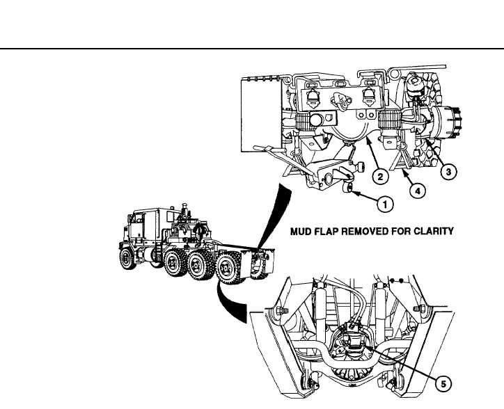
Place floor jack (1) under differential (2).
NOTE
Ride height is measured between
axle housing and bottom of frame.
(2)
Raise differential (2) with floor jack (1) to
achieve 9 in. (23 cm) 1/2 in. ride height
clearance.
(3)
Support axle (3) with jackstands (4).
NOTE
·
Driveline angle of axles no. 2 and
3, should be 3.0 degrees. Axle
no. 4 should have driveline angle
of 4.3 degrees.
·
If measurement taken in step (4)
is correct, go to step (9).
(4)
Position combination square on input yoke
(5) to check driveline angle.
10-33
|