|
| |
TM 9-2320-360-34-1
(16.1)
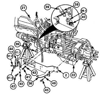
Remove locknut (37.1), screw (37.2), and
clip (37.3) from engine dipstick tube (39)
and engine dipstick tube support bracket
(44).
NOTE
Some engines do not have copper
washer.
(17)
Loosen collar (38) and remove engine
dipstick tube (39) and copper washer
(39.1) from adapter (40). Discard washer.
(18)
Remove two screws (41), six screws (42),
eight
lockwashers
(43),
and
engine
dipstick tube support bracket (44) from left
cradle (2) and engine/transmission (21
and 22). Discard lockwashers.
WARNING
Cradle weighs approximately 30 lb
(13.6 kg). Properly support cradle
during removal. Failure to comply
may result in injury to personnel.
(19)
Remove four screws (45), lockwasher,
(46), transmission dipstick tube support
bracket (36), and left cradle (2) from
transmission (22) with aid of assistant.
Discard lockwashers.
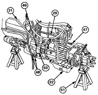
(20)
Install
three
screws
(47)
on
air
compressor (29).
WARNING
Grade 8 screws must be used to
support engine. Failure to comply
may cause engine to fall and result in
personnel injury.
NOTE
Screws should be installed 1.25 in.
(3.18
cm)
into
engine
flywheel
housing.
(21)
Install
four
screws
(48)
into
engine
flywheel housing (49) right and left side
bottom holes (50).
NOTE
Engine/transmission should be raised
enough to allow transmission lift to be
positioned under transmission.
(22)
Lift engine/transmission (21 and 22) and
remove jackstand (51) from rear of
transmission (22).
Change 1 7-9
|