|
| |
TM 9-2320-360-34-1
NOTE
Step (18) applies only to DDEC II
vehicles.
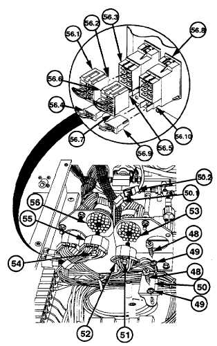
(18)
Remove two screws (48) and lockwashers
(49) from DDEC diagnostic connector
(50). Discard lockwashers.
NOTE
Steps (18.01) and (18.02) apply only
to DDEC Ill.
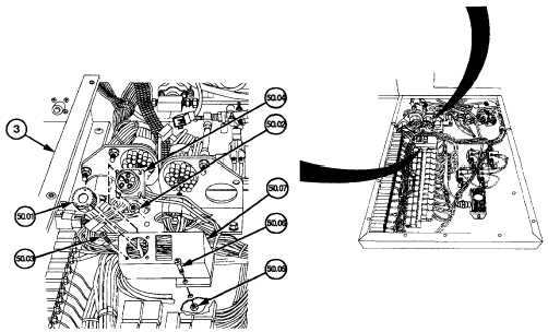
(18.01)
Remove cap (50.01), four nuts (50.02),
and four machine screws (50.03) from
harness (50.04).
(18.02)
Remove two nuts (50.05), two screws
(50.06),
and
bracket
(50.07)
from
electronic control box (3).
(18.1)
Remove electrical connector (50.1) from
cab wire harness connector (50.2).
(19)
Loosen screw (51) and remove black
electrical connector (52) from receptacle
(53).
(20)
Loosen screw (54) and remove white
electrical connector (55) from receptacle
(56).
(20.1)
Release tab (56.1) and remove connector
(56.2) from switch (56.3).
(20.2)
Remove
connector
(56.4)
and
light
assembly (56.5) from switch (56.3).
(20.3)
Release tab (56.6) and remove connector
(56.7) from switch (56.8).
(20.4)
Remove
connector
(56.9)
and
light
assembly (56.10) from switch (56.8).
Change 3 6-167
|