|
| |
TM 9-2320-360-34-1
6-7. REAR CAB WIRE HARNESS REPLACEMENT
This task covers:
a. Removal
c. Follow-On Maintenance
b. Installation
INITIAL SETUP
Equipment Condition
Materials/Parts
Batteries disconnected (TM 9-2320-360-20).
Ties, Cable, Plastic (Item 60, Appendix B)
Back seat cushion/frame removed
Gaskets (5) (Item 15, Appendix F)
(TM 9-2320-360-10).
Lockwasher (Item 118, Appendix F)
Footrest removed (TM 9-2320-360-10).
Snap Clips (12) (Item 323, Appendix F)
Ventilator lower plenum chamber removed
Snap Clips (5) (Item 324.1, Appendix F)
(TM 9-2320-360-20).
Snap Clip (Item 324.2, Appendix F)
Tools and Special Tools
Tool Kit, Genl Mech (Item 202, Appendix E)
a.
Removal
NOTE
· Electrical connectors are removed
by gently prying on tab and pulling
on connector.
· Snap clips are unlocked by pulling
lock button out.
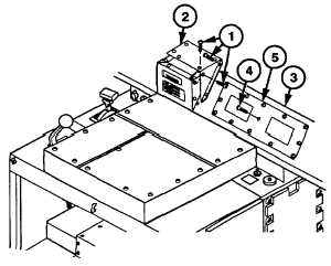
(1)
Remove nine screws (1) and panel (2)
from dash (3).
(2)
Remove 13 screws (4) and panel (5) from
dash (3).
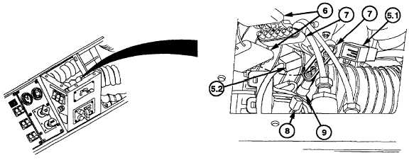
(2.1)
Remove electrical connector (5.1) from
cab wire harness connector (5.2)
(3)
Remove two rear cab light harness
connectors (6) from cab wire harness
connectors (7).
(4)
Remove electrical connector (8) from rear
heater switch electrical connector (9).
Change 1 6-69
|