|
| |
TM 9-2320-360-34-1
(5)
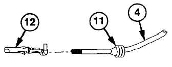
Install 1 in. (2.5 mm) of wire no. 1189 (4)
through new wire seal (11).
CAUTION
Strip wire after placing it through seal
to prevent damage to individual cable
strands.
(6)
Using wire strippers, strip end of wire no.
1189 (4) leaving 0.25 in. (0.64 cm) of
bare wire.
NOTE
Use proper hole according to gage of
wire.
(7)
Insert new terminal (12) in locating hole of
crimping tool.
(8)
Slide seal (11) down to end of insulation
on wire no. 1189 (4).
NOTE
Wire and seal should be positioned
so larger wings of terminal will crimp
around seal and smaller wings will
crimp around exposed bare wire.
(9)
Position wire no. 1189 (4) on terminal
(12).
(10)
Press handles of crimping tool together
until
ratchet
releases
and
crimp
is
complete.
(11)
Repeat steps (5) thru (10) for ground wire
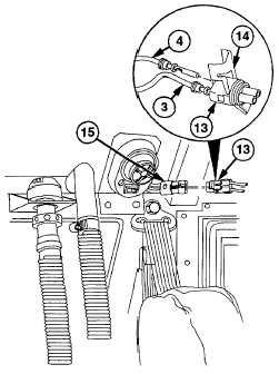
no. 1435 (3).
(12)
Install wire no. 1189 (4) in A position and
ground wire no. 1435 (3) in B position on
connector (13).
NOTE
Connector must be snapped closed
after wires are inserted.
(13)
Close and latch secondary lock (14) on
connector (13).
(14)
Install electrical connector (13) in left map
light connector (15).
6-59
|