|
| |
TM 9-2320-360-34-1
6-5. STEERING COLUMN HARNESS/SWITCH REPLACEMENT
This task covers
a. Removal
c. Follow-On Maintenance
b. Installation
INITIAL SETUP
Equipment Conditions
Materials/Parts
Steering wheel removed (TM 9-2320-360-20).
Socket, Contact (Item 325, Appendix F)
Turn signal handle removed
Terminals (6) (Item 330, Appendix F)
(TM 9-2320-360-20).
Wire Seals (6) (Item 345, Appendix F)
Wire Seal (Item 346, Appendix F)
Tools and Special Tools
Tool Kit, Electrical Repair (Item 201,
Appendix E)
Tool Kit, Genl Mech (Item 202, Appendix E)
a.
Removal
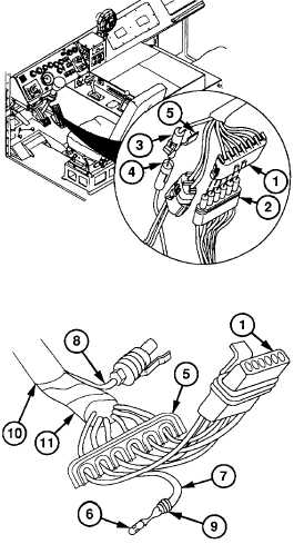
NOTE
Connector is removed by gently
prying up on dip and pulling on
connector.
(1)
Remove 6-pin electrical connector (1)
from electrical connector (2).
(2)
Remove horn button electrical connector
(3) from electrical connector (4).
(3)
Unlatch and open secondary lock (5) on
two connectors (1 and 3).
(4)
Insert pin removal tool in cavity on
connector
(1)
until seated to release lock tangs on
terminal (6).
(5)
Pull wire (7) back, turn connector (1), and
remove tool.
(6)
Repeat steps (4) and (5) for remaining five
wires (7) and horn button wire (8).
NOTE
Do not cut terminal from yellow horn
button wire.
(7)
Cut terminals (6) directly behind wire seals
(9)
on six wires (7). Discard terminals and
seals.
(8)
Remove wire casing (10) from wire
harness (11) and horn button wire (8).
6-43
|