|
| |
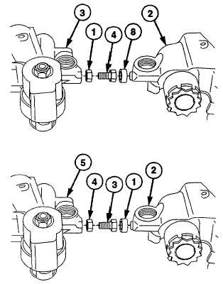
TM 9-2320-360-34-1
3-26. ENGINE BRAKE RETARDER REPLACEMENT (CONT)
(5)
Remove connector (4) and nut (1) from
left brake (3).
(6)
Remove seal ring (8) from right brake (2).
Discard seal ring.
(7)
Repeat steps (1) thru (6) for remaining
right and left brakes.
b.
Installation
(1)
Install new seal ring (1) in right brake (2).
(2)
Install connector (3) with nut (4) in left
brake (5).
(3)
Screw in connector (3) about 1/2 in. (13
mm).
NOTE
Engine mounting surface must be
clean before positioning right and left
brakes on engine.
(4)
Position master piston fork assembly (6)
over injector rocker clevis (7).
(5)
Install right brake (2) and left brake (5)
with four mounting screws (8) through
rocker arm shaft (9) to cylinder head (10).
(6)
Tighten screws (8) to 45 lb-ft (61 Nm).
(7)
Tighten screws (8) to 88-92 lb-ft (119-124
Nm).
(8)
Move master piston fork assembly (6) up
and down several times to make sure it
rides freely on injector rocker clevis (7).
3-134
|