|
| |
TM 9-2320-360-34-1
3-11. VALVE BRIDGE REPAIR (CONT)
(8)
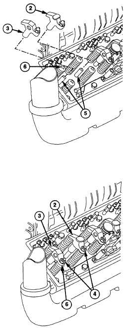
Coat valve bridge (2 or 3) and valve
bridge guide (5) with lubricating oil.
(9)
Install valve bridge (2 or 3) on valve bridge
guide (5) making sure groove in bridge fits
over top of valve stem (6).
(10)
Insert one 0.0015 in. feeler gage between
front end of valve bridge (2 or 3) and
exhaust valve stem (6).
(11)
Insert one 0.0015 in. feeler gage between
rear end of valve bridge (2 or 3) and
exhaust valve stem (6).
(12)
Press down firmly on top center of valve
bridge (2 or 3) and check that both feeler
gages are tight.
(13)
Remove both feeler gages.
NOTE
Do step (14) if feeler gages are not
tight.
(14)
Place valve bridge (2 or 3) in soft-jawed
vise and loosen nut (4). Repeat steps (3)
thru
(13)
until
proper
clearance
is
obtained.
(15)
Repeat steps (1) through (14) for 15
remaining valve bridges.
c.
Follow-On Maintenance
Install rocker arms (para 3-18).
INJECTOR REMOVED FOR CLARITY
3-84
|