 |
|||
|
|
|||
|
Page Title:
Crankshaft Main Bearings - Remove |
|
||
| ||||||||||
|
|
 TM 9-2320-312-24-2
Truck Engine
Disassembly and Assembly Section
Start By:
a. Remove the engine oil pump. Refer to
Disassembly and Assembly, "Engine Oil Pump -
Remove".
NOTICE
Keep all parts clean from contaminants.
Contaminants may cause rapid wear and shortened
component life.
g00678202
Illustration 226
13. Place index mark (7) on the connecting rod.
Place index mark (9) on connecting rod cap
nut (1). Index marks (7) and (9) mark the initial
position of the nut. Place index mark (8) on
connecting rod cap nut (1). Index mark (8)
should be 60 5 degrees counterclockwise
from index mark (9). Tighten each nut (1) for
an additional 60 5 degrees (1/6 turn). Index
mark (8) should be lined up with index mark (7).
Repeat the procedure for the other connecting
g00610152
rod cap nut.
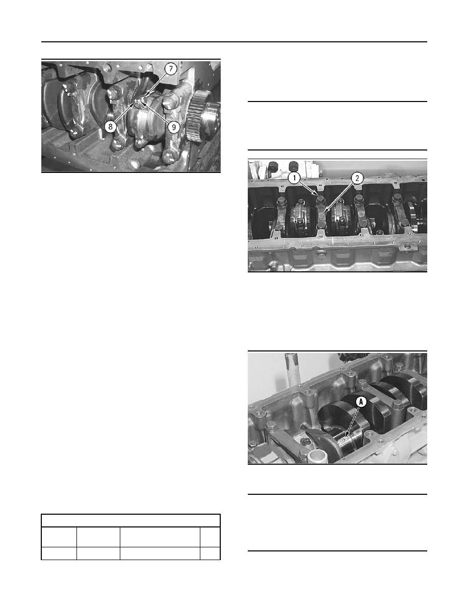
Illustration 227
1. Remove bolts (1) that hold crankshaft main
14. Repeat Steps 1 through 13 for the remaining
bearing cap (2). Remove crankshaft main
pistons and connecting rods.
bearing cap (2).
End By:
2. Remove the lower half of the crankshaft main
bearing from crankshaft main bearing cap (2).
a. Install the piston cooling jets. Refer to
Disassembly and Assembly, "Piston Cooling Jets
- Remove and Install".
b. Install the engine oil pump. Refer to Disassembly
and Assembly, "Engine Oil Pump - Install".
c. Install the cylinder head. Refer to Disassembly
and Assembly, "Cylinder Head - Install".
i01747897
Crankshaft Main Bearings -
Remove
g00516920
SMCS Code: 1203-011
Illustration 228
Typical example
Removal Procedure
NOTICE
Table 42
If the crankshaft is turned in the wrong direction, the
tab of the crankshaft main bearing will be pushed be-
Required Tools
tween the crankshaft and the cylinder block. this can
Part
cause damage to either or both the crankshaft and the
Tool
Part Description
Qty
Number
cylinder block.
1
2P-5518
A
Bearing Tool
3. Use the following steps in order to remove the
upper half of crankshaft main bearings:
|
|
Privacy Statement - Press Release - Copyright Information. - Contact Us |
