 |
|||
|
|
|||
|
Page Title:
Camshaft Gear - Remove and Install |
|
||
| ||||||||||
|
|
 TM 9-2320-312-24-2
Truck Engine
Disassembly and Assembly Section
1. Wrap the camshaft with a protective covering in
2. Ensure that the timing marks on the following
order to prevent damage to the camshaft.
gears are aligned: the camshaft drive gear, the
idler gear, and the crankshaft gear.
g00611152
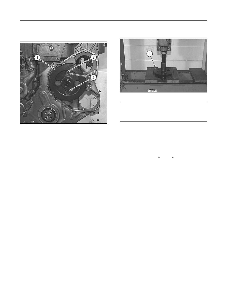
Illustration 204
NOTICE
Do not allow the camshaft to fall to the floor when
pressing it from the drive gear. Also make sure that
the camshaft lobes do not catch on the press plates.
g00611074
Illustration 203
2. Place the camshaft and camshaft gear (1) in a
suitable press. Press the camshaft from camshaft
Typical example
gear (1).
3. Install camshaft retainer plate (2) and two bolts
(3) on camshaft gear (1).
Installation Procedure
End By:
1. Heat the camshaft gear to a maximum
temperature of 315 C (600 F).
a. Install the front cover. Refer to Disassembly and
Assembly, "Front Cover - Install".
2. Align the key in the camshaft with the groove
(keyway) in the camshaft gear.
b. Install the side cover. Refer to Disassembly and
Assembly, "Lifter Group - Remove and Install".
3. Install the camshaft gear on the end of the
camshaft.
c. Install the unit injector hydraulic pump. Refer
to Disassembly and Assembly, "Unit Injector
End By:
Hydraulic Pump - Install".
a. Install the camshaft. Refer to Disassembly and
d. Install the rocker arms and the pushrods. Refer
Assembly, "Camshaft - Install".
to Disassembly and Assembly, "Rocker Shaft
and Pushrod - Install".
i01151709
Camshaft Gear - Remove and
Install
SMCS Code: 1210-010-GE
Removal Procedure
Start By:
a. Remove the camshaft. Refer to Disassembly and
Assembly, "Camshaft - Remove".
|
|
Privacy Statement - Press Release - Copyright Information. - Contact Us |