 |
|||
|
|
|||
|
|
|||
| ||||||||||
|
|
 TM 9-2320-312-24-2
Truck Engine
Disassembly and Assembly Section
Note: The air compressor was removed in order to
i01747719
accommodate the engine repair stand.
Camshaft - Install
1. Turn the crankshaft to top center compression
SMCS Code: 1210-012
stroke for the No. 1 piston. Install the timing
bolt in the flywheel. This is for timing during
Installation Procedure
installation.
2. Ensure that the timing marks on the following
NOTICE
gears are aligned: the camshaft drive gear, the
Care must be taken to ensure that fluids are contained
idler gear, and the crankshaft gear.
during performance of inspection, maintenance, test-
ing, adjusting and repair of the product. Be prepared to
Note: It is not necessary to remove the cylinder
collect the fluid with suitable containers before open-
head for removal of the camshaft.
ing any compartment or disassembling any compo-
nent containing fluids.
3. Wire the valve lifters away from the camshaft.
Refer to Special Publication, NENG2500, "Caterpillar
Tools and Shop Products Guide" for tools and supplies
suitable to collect and contain fluids on Caterpillar
products.
Dispose of all fluids according to local regulations and
mandates.
NOTICE
Keep all parts clean from contaminants.
Contaminants may cause rapid wear and shortened
component life.
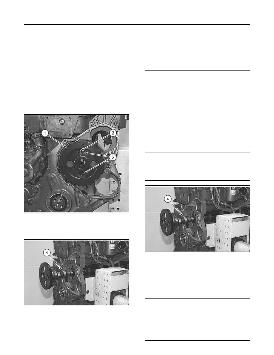
g00611074
Illustration 200
4. Remove two bolts (3) and camshaft retainer plate
(2) from camshaft gear (1).
g00611082
Illustration 202
Typical example
Note: The air compressor was removed in order to
accommodate the engine repair stand.
1. Carefully install camshaft (4) in the cylinder
block.
NOTICE
When installing the camshaft, make sure the num-
g00611082
Illustration 201
ber one cylinder is at top center of the compression
stroke with the timing bolt installed in the flywheel. The
5. Remove camshaft (4) from the cylinder block.
camshaft timing is very important. The timing mark
on the camshaft drive gear must line up with the tim-
ing mark on the idler gear. Refer to the Specifications
Manual for more information.
|
|
Privacy Statement - Press Release - Copyright Information. - Contact Us |
