 |
|||
|
|
|||
|
|
|||
| ||||||||||
|
|
 22
TM 9-2320-312-24-2
Truck Engine
Disassembly and Assembly Section
6. Secure the wiring harness to the unit injector
hydraulic pump with a nylon strap. Connect
electrical plugs (3) and (4).
Note: Use the following steps in order to convert the
engine from the 151-0858 Tube to the 175-3236
Hose Assembly.
7. Remove the connectors for the 151-0858 Tube
that are located in the unit injector hydraulic
pump and the cylinder head.
8. Position the 153-4906 O-Ring Seal on the
threaded end of each 179-7002 Adapter. Install
the adapters in the unit injector hydraulic pump
and the cylinder head.
Note: When you replace the 151-0858 Tube with
175-3236 Hose Assembly the fuel supply line
must be replaced in order to provide the necessary
clearance.
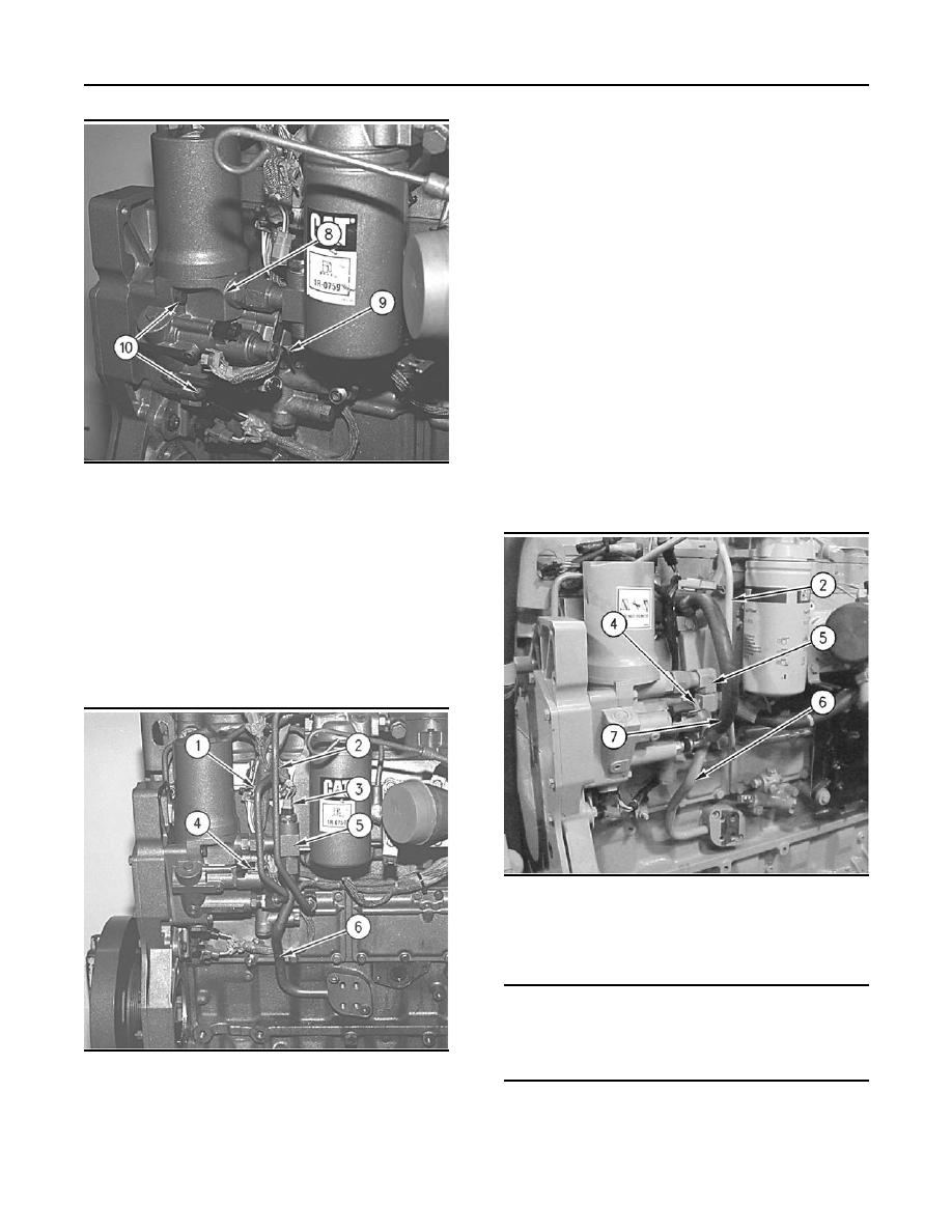
g00706976
Illustration 49
Note: The following steps are for engines that are
equipped with the 175-3236 Hose Assembly.
3. Position unit injector hydraulic pump (8) on the
timing gear housing. Install three bolts (10) and
tighten three bolts (10) to a torque of 28 7 Nm
(20 5 lb ft).
Note: If the engine is equipped with a 175-3236
Hose Assembly then go to Step 9. If the engine
is equipped with a 151-0858 Tube then proceed
with Step 4. If you are converting the engine from
151-0858 Tube to 175-3236 Hose Assembly then
go to Step 7.
g00706904
Illustration 51
9. Install return line (6) and fitting (5).
10. Reconnect electrical plug (4).
NOTICE
If the hose is not correctly connected the hose will
come loose when the engine is started and the en-
gine oil will come out of the hose. Engine damage can
g00616113
Illustration 50
result.
4. Install return line (6) and fitting (5).
5. Install tube (1) and fuel line (2).
|
|
Privacy Statement - Press Release - Copyright Information. - Contact Us |