 |
|||
|
|
|||
|
Page Title:
Check the Fuel System for Leaks |
|
||
| ||||||||||
|
|
 15
TM 9-2320-312-24-2
Truck Engine
Disassembly and Assembly Section
7. Insert the harness connectors (2) back into the
injectors' solenoids. Ensure that the clips are
snapped back into the proper position.
8. Check the system for leaks by using the following
procedure.
Check the Fuel System for Leaks
1. Visually inspect the components of the injector
for oil leaks around the outside diameter.
g00312124
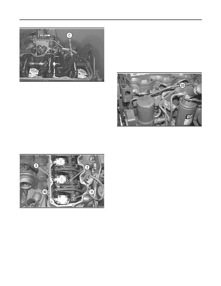
Illustration 31
(C) 152-1057 Fuel Injector Installer
5. Carefully install the injector into the injector bore.
If access permits you to seat the injector, push
the injector straight down on top of the injector's
solenoid by hand until the injector is firmly
seated in the injector bore. Pushing hard enough
to compress the injector's seals may be difficult.
If the injector can not be seated by hand, use a
152-1057 Fuel Injector Installer (C).
g00778891
Illustration 33
Note: Do NOT pry on the top of the injector with
another tool. Do NOT strike the injector with a
2. Disconnect the injector wiring harness with
hammer. Damage to the injector will result. Damage
the 12-pin connector (20). The harness is
to the injector that is due to improper installation is
located between the hydraulic pump and the
not a warrantable failure.
cylinder head. Disconnect the Injection Actuation
Pressure Sensor's connector. This will cause the
oil pressure to raise to about 2500 psi.
3. Crank the engine in order to allow the actuation
pressure to rise. Cranking the engine also purges
the air from the system.
4. Visually check for oil leaks in the area that is
between the outside diameter of the injector and
the cylinder block.
Note: A small amount of seepage from the injector's
vent hole during cranking is normal. A large steady
flow from one injector that is greater than the flow
from the other injectors may indicate a problem with
g00778888
Illustration 32
that injector.
(2) Wiring Harness Connection
(3) Clamp
5. If no leaks are found, connect the injector wiring
(10) Shoulder Bolt
harness (20) and the Injection Actuation Pressure
(11) Socket Head Bolt
Sensor.
Note: Do not use the shoulder bolt and the socket
6. Start the engine.
head bolt in order to seat the injector. If a side load
is placed on the bolts, the bolts may fail.
7. Check for oil leaks while the engine is running
at idle.
6. After the injector is seated, position the clamp
(2) and tighten the Shoulder Bolt (10) to a torque
8. If no leaks are found, install the ET or other
of 6 Nm (50 lb in). Then tighten the Socket Head
electronic service.
Bolt (11) to a torque of 12 Nm (9 lb ft).
|
|
Privacy Statement - Press Release - Copyright Information. - Contact Us |
