 |
|||
|
|
|||
|
Page Title:
Test Step 3. Measure the Sensor Resistance Through the Engine Harness |
|
||
| ||||||||||
|
|
 257
TM 9-2320-312-24-2
Troubleshooting Section
Test Step 3. Measure the Sensor
Resistance Through the Engine Harness
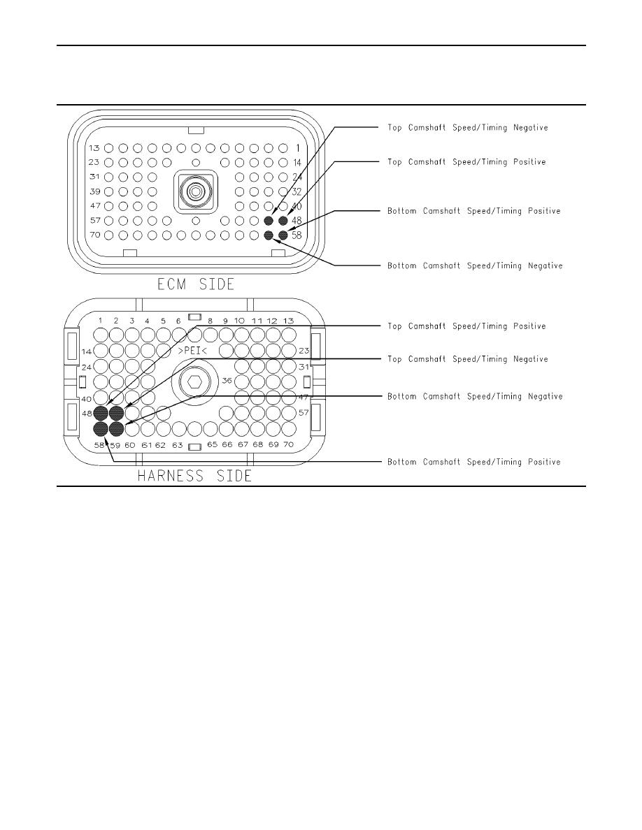
g00864786
Illustration 93
Terminal locations for ECM connector P2
D. Ensure that the latch tab on the connector is
A. Turn the ignition key switch to the OFF position.
properly latched and ensure that the latch tab is
fully latched.
B. Thoroughly inspect ECM vehicle harness
connector J2/P2. Refer to Troubleshooting,
E. Check the ECM connector (allen head screw) for
"Electrical Connectors - Inspect" for details.
the proper torque of 6.0 Nm (55 lb in).
C. Perform a 45 N (10 lb) pull test on the following
F. Repair the harness or repair the connector if a
wires in the ECM engine harness connector P2
problem is found.
that are associated with the engine speed/timing
sensors:
G. Ensure that the wiring harness is correctly routed
P2:48
and secured at the proper locations.
P2:49
H. Ensure that the harness wiring is not pulled
too tightly. When the harness wiring is pulled
P2:58
too tightly, vibrations or movement can cause
intermittent connections.
P2:59
I. Inspect the harness wiring for nicks and
abrasions.
Refer to Illustration 93.
J. If the harness and the connector are OK,
disconnect ECM connector J2/P2.
|
|
Privacy Statement - Press Release - Copyright Information. - Contact Us |